2OM-1011-002.pdf - 第253页
0305-001 Tg0858-PM-PM 2. NOZZLE TYPE DA T A Display POSITION X (Horizontal), Y (V ertical) The set parameters are used to specify the center position of Pick-Up Hole (1) based on the nozzle center . • Data Input Range X:…
0305-001 Tg0858-PM-PM
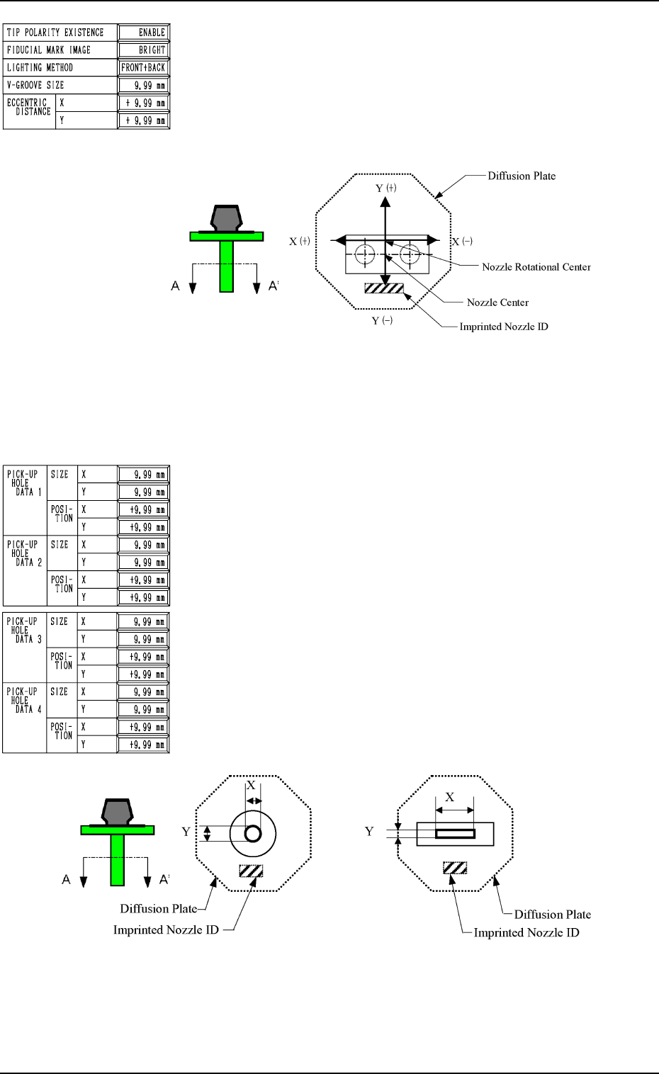
ECCENTRIC DISTANCE X (Horizontal) and Y (Vertical)
In the case of the special nozzle whose tip is manufactured
eccentrically from the head rotational center, set the eccentric-
ity (distances) separately in the “X” and “Y” data boxes.
• Data Input Range
0 to 99.99 mm
Specify X and Y as shown in the following figure.
Fig. 2H11 Sectional View A-A’
(Eccentric Designation: X = 0 and Y = Minus)
Set the data values (X, Y) as “0, 0” for a standard nozzle.
Second Page
PICK-UP HOLE DATA 1, 2, 3, 4
SIZE X (Horizontal), Y (Vertical)
Set the dimensions of the nozzle pick-up hole in the data boxes.
In the case of “ROUND”, set the same dimensions for “X”
and “Y”.
Set X and Y as shown in the following figure. in the case of a
rectangle.
• Data Input Range
X: 0 to 99.99
Y: 0 to 99.99
Fig. 2H13 Sectional View A-A’
2. NOZZLE TYPE DATA Display
8-5
Fig. 2H10
Fig. 2H12
0305-001 Tg0858-PM-PM
2. NOZZLE TYPE DATA Display
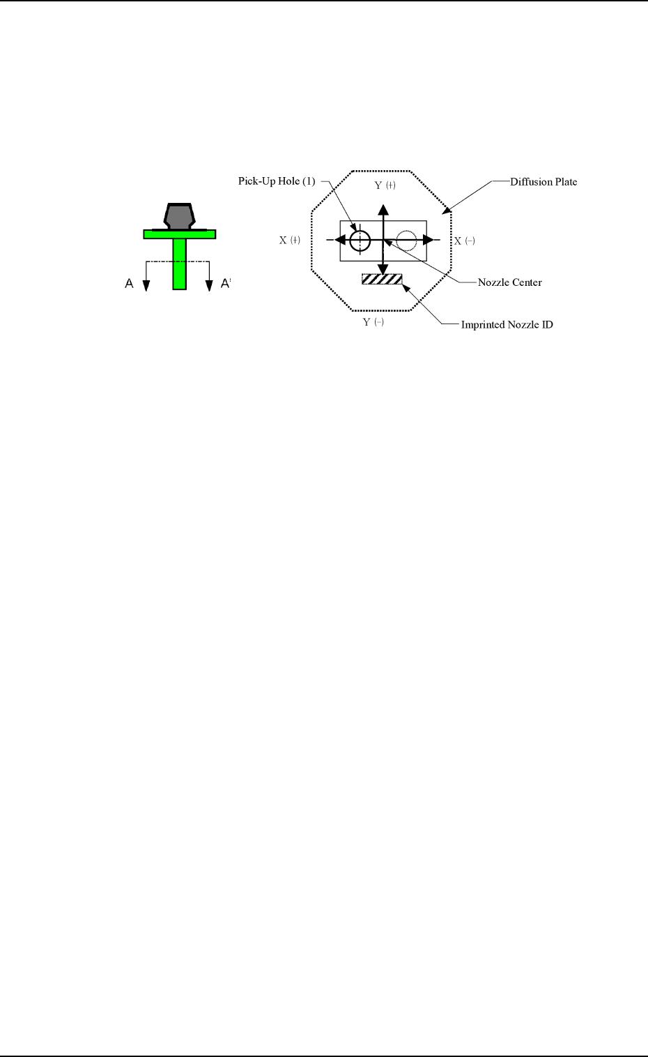
POSITION X (Horizontal), Y (Vertical)
The set parameters are used to specify the center position of
Pick-Up Hole (1) based on the nozzle center.
• Data Input Range
X: 99.99 to +99.99
Y: 99.99 to +99.99
Set X and Y as shown in the following figure.
Fig. 2H14 Sectional View A-A’
When no relevant hole is found, set the data values (X, Y) as
“0, 0”.
Up to 4 pieces of pick-up holes can be specified.
Operation
• Press the data key to be edited and use the ten-key pad or the
option keys to enter a parameter. Then, press the [SET] key.
• When the [RTN] key is pressed, the “NOZZLE TYPE DATA
SAVE MODE” display appears on the screen.
Note: When a special nozzle is attached, the nozzle type data
must be registered as new one.
8-6
0305-001 Tg0858-PM-PM
*2
*3
*1
Fig. 2H15
Fig. 2H16
[CHNG] Key
*4
*4
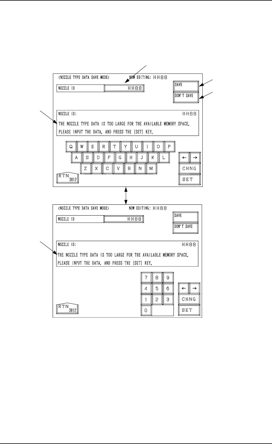
3. NOZZLE TYPE DATA SAVE MODE Display
*1 NOZZLE ID
When the data box of the label “NOZZLE ID” is pressed, a parameter can
be entered in the data box.
Enter a new nozzle ID and press the [SET] key. A new nozzle is registered
with the entered ID.
*2 [SAVE] Key
The created nozzle data is saved.
When the same nozzle ID exists, another “NOZZLE TYPE DATA SAVE
MODE” display (Fig. 2H17) appears on the screen, enabling the selection
of whether or not the nozzle data should be replaced with the existing one.
*3 [DON’T SAVE] Key
When the [DON’T SAVE] key is pressed, the edited nozzle type data is not
saved.
Note: When there is not enough memory capacity, the message is issued at
*4 and the modified data cannot be saved.
3. NOZZLE TYPE DATA SAVE MODE Display
When the [RTN] key is pressed at the “NOZZLE TYPE DATA” display (Fig.
2H2), the following display appears on the screen.
Every time the [CHNG] key is pressed, the display changes.
8-7