2OM-1011-002.pdf - 第66页
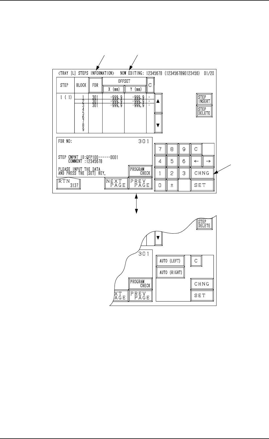
0305-001 Tg0858-PM-PM 2-47 *1 [FDR] Key Set the type of components (FDR NO) for each individual step Nos. and blocks. *2 OFFSET X (mm), Y (mm) Set the coordinates of the tray origin corner to be positioned when a tray is…
0305-001 Tg0858-PM-PM
*1
*2
Fig. 2B96
[CHNG] Key
A
2-46
When the [1 ( 1)] key is pressed at the display for “TRAY L” (Fig. 2B95) , the
following display appears on the screen.
Note: The [CHNG] key A appears only when the [X (mm)] key under “OFF-
SET” is selected.
2.5 COMPONENT DATA Display
Fig. 2B97
0305-001 Tg0858-PM-PM2-47
*1 [FDR] Key
Set the type of components (FDR NO) for each individual step Nos. and
blocks.
*2 OFFSET X (mm), Y (mm)
Set the coordinates of the tray origin corner to be positioned when a tray is
set in the pallet. The coordinates must be determined based on the pallet
reference position.
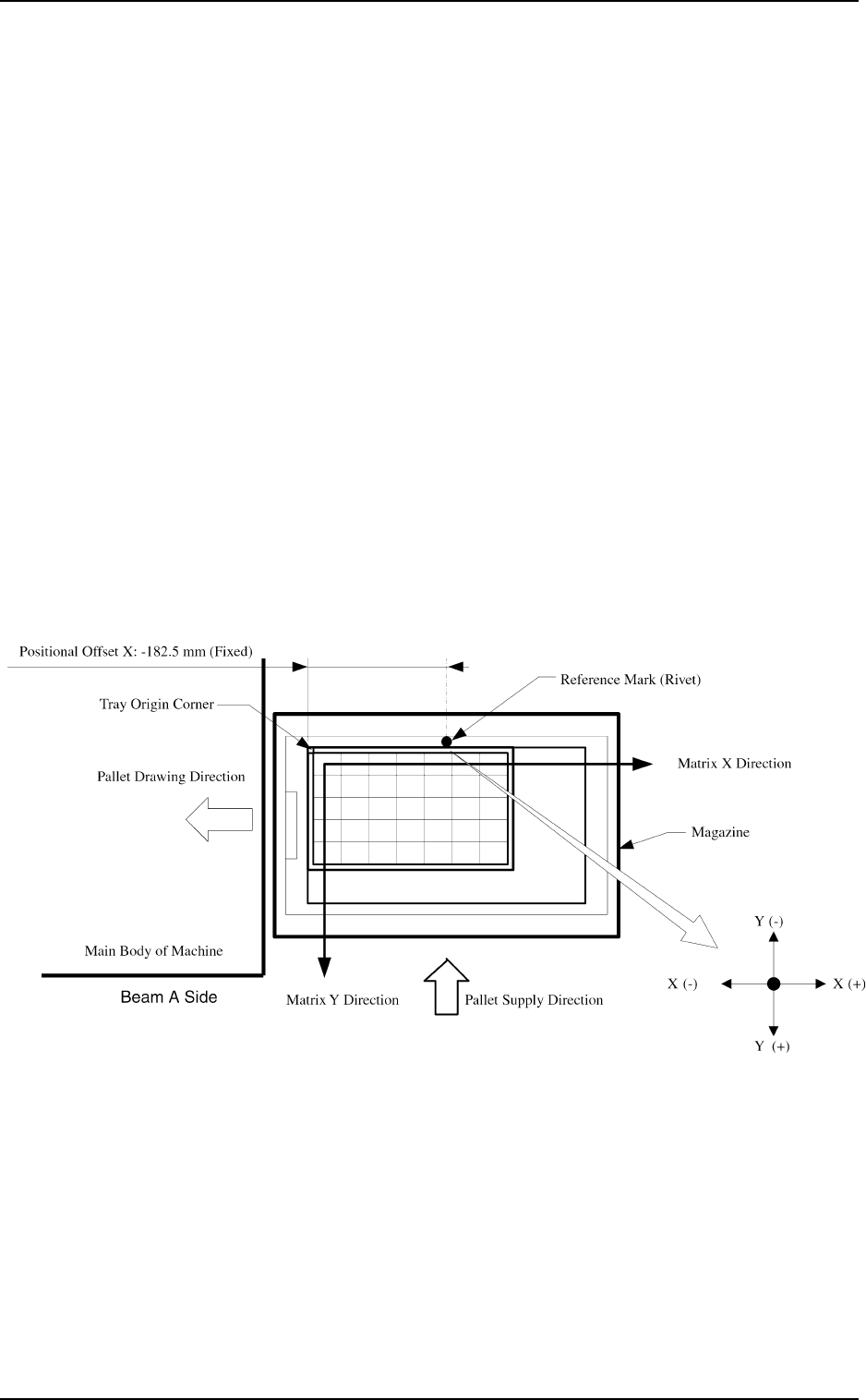
Note: The coordinates to be entered as positional offset are based on the
reference mark and fixed regardless of whether Tray L or R is used.
• When several trays are put on one pallet (when several blocks are used),
it is required to set positional offsets (X and Y) for each individual blocks.
By specifying the tray origin corner position, the pick-up position of
each tray is automatically calculated based on the component library data.
(“SIDE”, “PITCH”, “MATRIX”, etc.)
Case: Tray L
It is recommended that the tray should be set as shown the following figure
to ensure the X/Y-beam movable range as wide as possible. In this case,
select the [AUTO (LEFT)] key.
• When one tray is set on one pallet and brought to the left side, the posi-
tional offset (X, Y) is fixed as “X = -182.5 mm” and “Y = +0.0 mm”.
2.5 COMPONENT DATA Display
Fig. 2B98
0305-001 Tg0858-PM-PM
Magazine
Pallet Drawing Direction
Main Body of Machine
Pallet Supply Direction
Reference Mark (Rivet)
Tray Origin Corner
Matrix Y Direction
Matrix X Direction
Positional Offset X
Beam A Side
X(+)X (-)
Y (-)
Y
(+)
Fig. 2B99
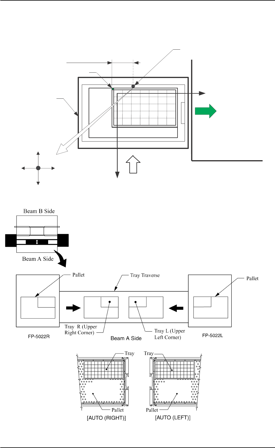
Ref.: [AUTO (LEFT)] and [AUTO (RIGHT)] Keys
“LEFT” or “RIGHT” represents the direction in which a
tray should be pushed when it is set on the pallet.
Any wasteful motion can be suppressed when Tray R is
set at the upper right corner of the pallet and Tray L at the
upper left corner as shown in the following figure.
Fig. 2B100
2-48
2.5 COMPONENT DATA Display
Case: Tray R
It is recommended that the tray should be set as shown in the following
figure to ensure the X/Y-beam movable range as wide as possible. In this
case, select the [AUTO (RIGHT)] key.