2OM-1011-002.pdf - 第92页
0305-001 Tg0858-PM-PM 3.2 Example 2 (Example of Placement Data Creation) 3.2.1 Normal Placement Data (1) Pattern Sample • The figure below shows an example of placing four components on the P .C.B. 3.2 Example 2 (Example…
0305-001 Tg0858-PM-PM2-72
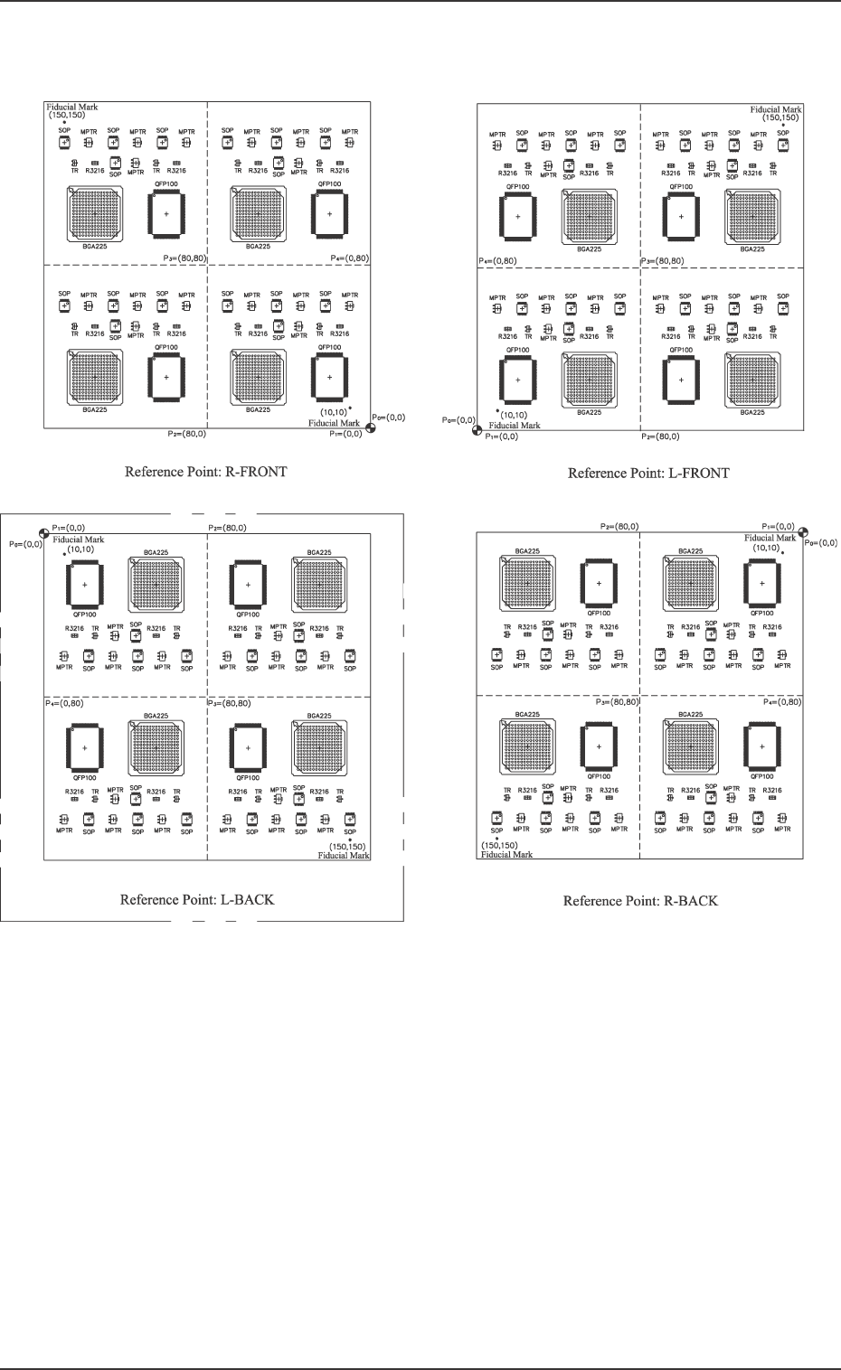
Parameters are based on the reference point “L-BACK”.
They change depending on where the reference point is specified.
Fig. 2B116 Examples of Component Placement Based on Difference in Reference Points
3.1 Example 1
0305-001 Tg0858-PM-PM
3.2 Example 2 (Example of Placement Data Creation)
3.2.1 Normal Placement Data
(1) Pattern Sample
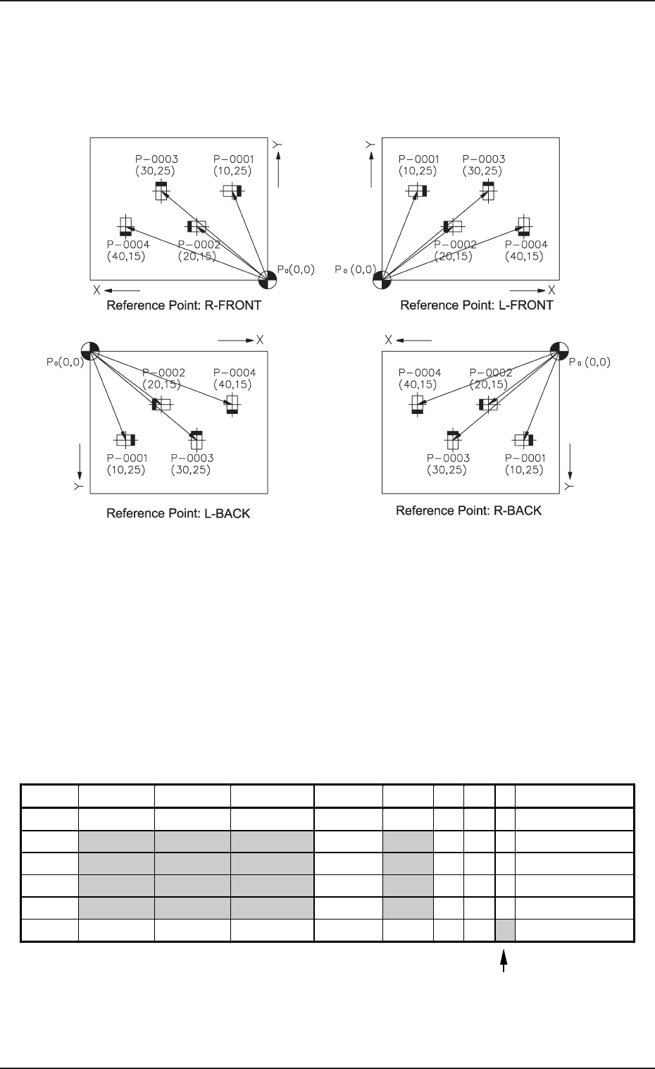
• The figure below shows an example of placing four components on the
P.C.B.
3.2 Example 2 (Example of Placement Data Creation)
Fig. 2B117
Notes: (a) P
0
shows the P.C.B. positioning reference.
(b) The placement coordinates of a component are measured based
on the P.C.B. positioning reference (0, 0).
(2) Example of Data Creation
• Use placement data (P) U01.
• Do not enter any parameters in placement data (O) because it is not
used.
When it is not necessary to perform any P.E.C. recognition on each
individual components, do not set any parameters as placement data
(V).
PLACEMENT DATA (P) U01
Enter “0” (zero) in all data fields of the last step and “E” as
a control command.
(Component placement is not implemented for the step where a
control command other than “-” and “D” is entered.)
P-NO. X(mm) Y(mm) Z(THETA) H(mm) FDR S V C COMMENT
0000 +0.00 +0.00 +0°00’ +0.00 000 - 00 -
0001 +10.00 +25.00 +0°00’ +0.00 101 - 00 -
0002 +20.00 +15.00 +180°00’ +0.00 201 - 00 -
0003 +30.00 +25.00 +90°00’ +0.00 301 - 00 -
0004 +40.00 +15.00 +270°00’ +0.00 601 - 00 -
0005 +0.00 +0.00 +0°00’ +0.00 000 - 00 E
2-73
Table 2B22
0305-001 Tg0858-PM-PM
3.2 Example 2 (Example of Placement Data Creation)
3.2.2 Normal Placement Data
[To set the P.E.C. recognition function for each
individual components]
(1) Pattern Sample
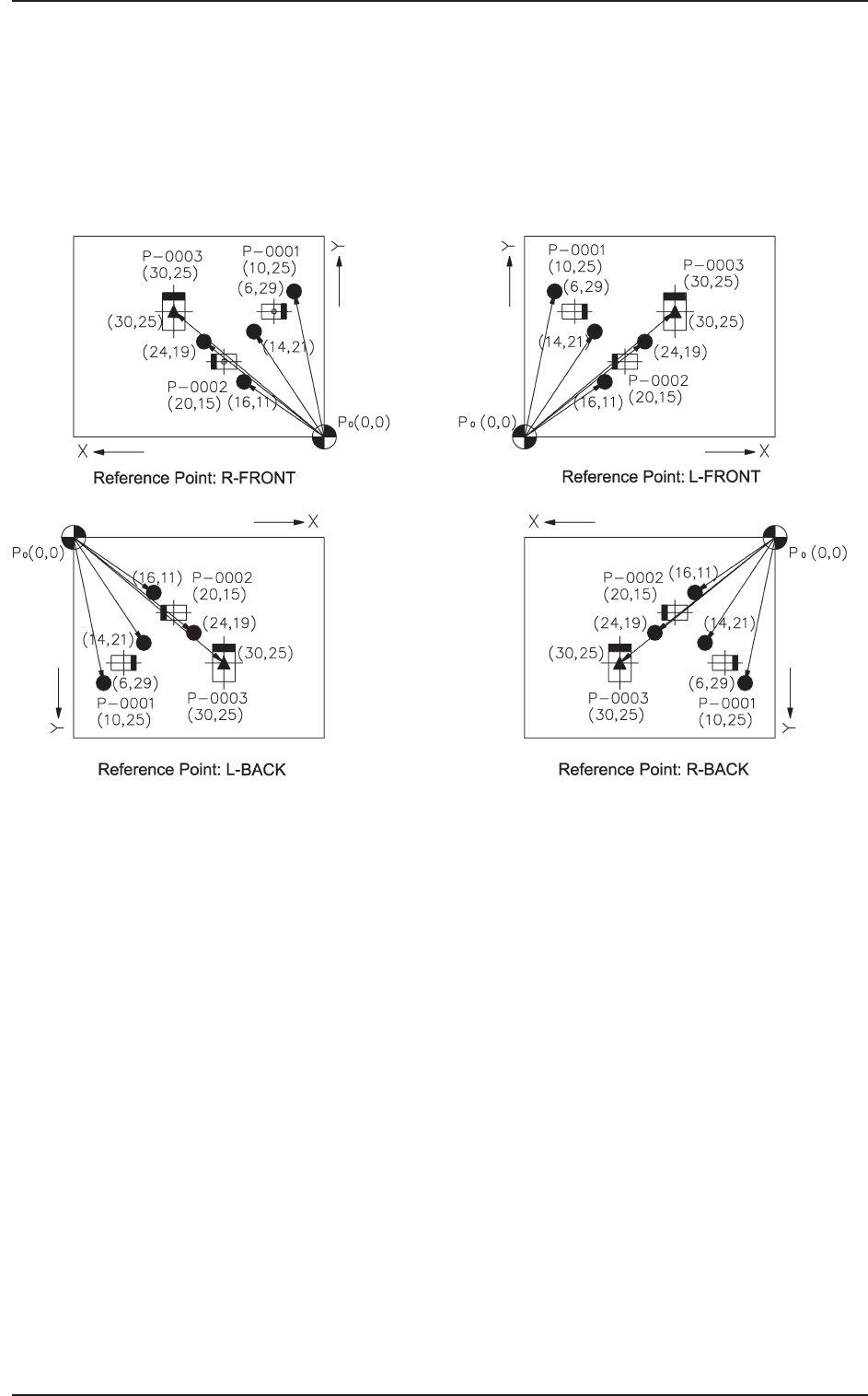
• The figure below shows an example of placing three components on
the P.C.B.
2-74
Fig. 2B118
Notes: (a) P
0
shows the P.C.B. positioning reference.
(b) The placement coordinates of a component are measured based
on the P.C.B. positioning reference (0, 0).
(c) The fiducial mark position of a component is measured based on
the P.C.B. positioning reference (0, 0).