2OM-1011-002.pdf - 第233页
0305-001 Tg0858-PM-PM 17. DA T A SA VE MODE Display When the [R TN] key is pressed at each display for offset data editing, the following display appears on the screen. 17. DA T A SA VE MODE Display Fig. 2E123 [SA VE] Ke…

0305-001 Tg0858-PM-PM5-51
16. HEAD OFFSET (GET BOTH IMAGE) Display
Reference
Subordinate Head:
When two steps are paired through the simultaneous pick-up or the pick-up priority func-
tion designated in the placement data, this head handles the component related to the step
No. larger than the other.
On the other hand, the head which handles the component related to the smaller step No. is
called “Guide Head”.
The simultaneous recognition is automatically prohibited and images are captured indi-
vidually when,
•
components which require BGA lighting are picked up.
•
a value other than “0” (zero) is set (designation of eccentric pick-up) in the “X” and “Y”
data boxes of the label “PICK-UP LOCATION CORRECTION” at the “CMPNT LI-
BRARY” display.
•
The visual field of the confronting camera cannot cover the components picked up by
the right and left heads.
In this case, the beams must be moved such that the rotational centers of the heads are lo-
cated at the camera centers before the images are captured.
Compared with this, in the case of the simultaneous recognition, the guide head (for the
smaller step) moves normally but the subordinate head faces the other one at the position
where the head rotational center does not match the camera center due to the relation be-
tween the head-to-head and camera-to-camera pitches. Therefore, this offset data is re-
quired for recognition processing and correction calculation.
0305-001 Tg0858-PM-PM
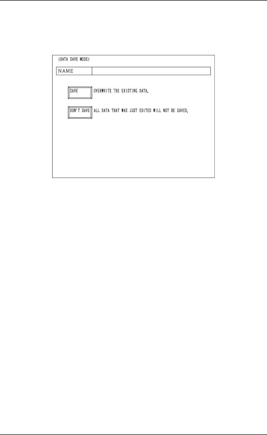
17. DATA SAVE MODE Display
When the [RTN] key is pressed at each display for offset data editing, the
following display appears on the screen.
17. DATA SAVE MODE Display
Fig. 2E123
[SAVE] Key : Press this key to save the data.
[DON’T SAVE] Key : Press this key not to save the data.
The data is not saved and the “OFFSET DATA” dis-
play (Fig. 2E1) appears on the screen.
Note: The edited parameters become invalid.
5-52

0305-001 Tg0858-PM-PM
Section 6
TEST MODE Display
6-A
This section explains the TEST RUN DATA display and opera-
tion procedures, etc.