2OM-1011-002.pdf - 第127页
0305-001 Tg0858-PM-PM 4.5 COMPONENT DA T A Display (1) When the [T APE [A] (F101-F139)], the [VIB STICK [A] (F141-F199)], or the [TRA Y L (F301-F599)] key is pressed at the “P A TTERN PRO- GRAM EDIT” display , the corres…
0305-001 Tg0858-PM-PM
4.4 SET-UP DATA Display
4.4 SET-UP DATA Display
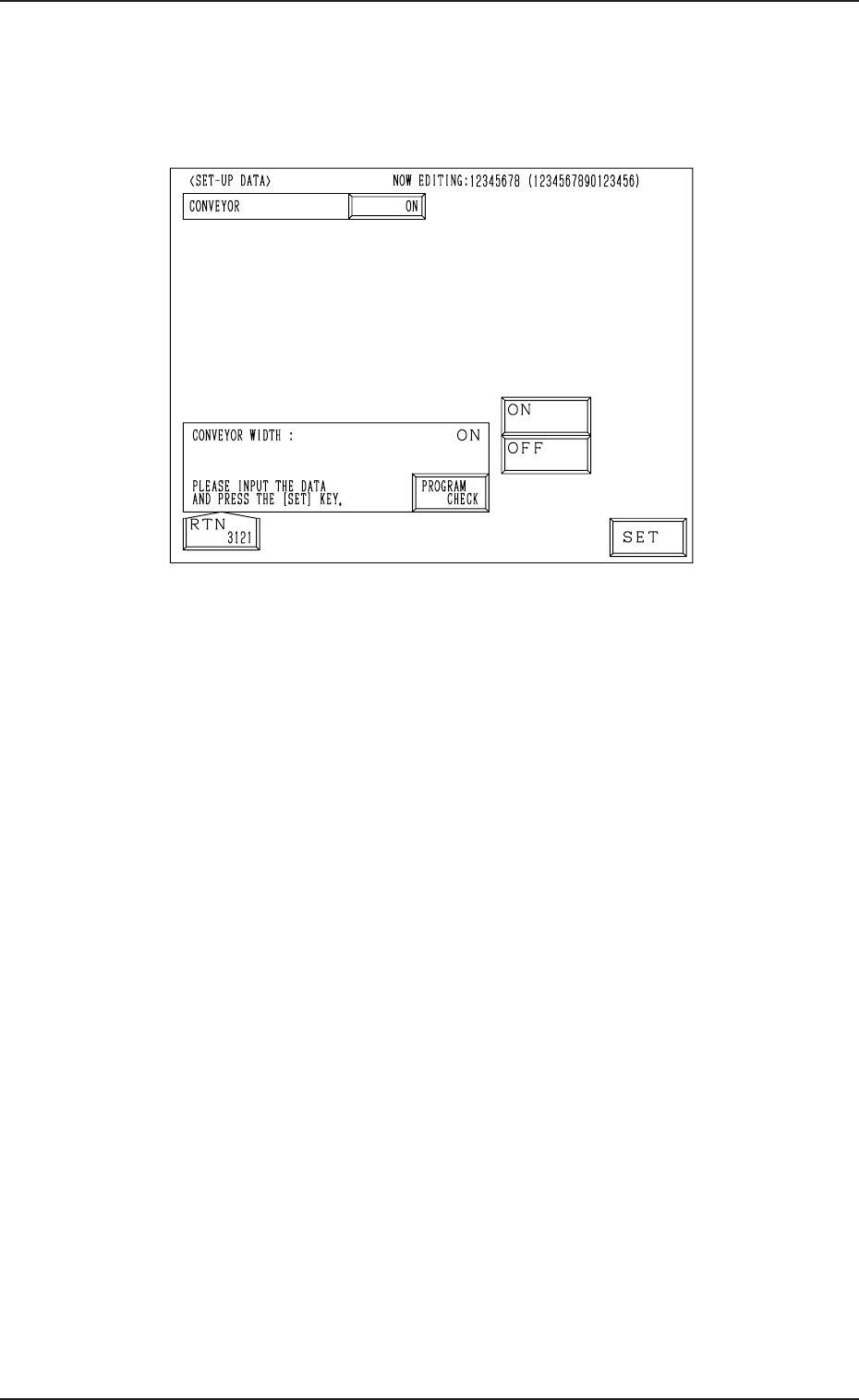
(1) When the [SET-UP DATA] key is pressed at the “PATTERN PROGRAM
EDIT” display, the following display appears on the screen.
Fig. 2B155
(2) Select the [ON] or the [OFF] key to determine whether or not the con-
veyor width should be set up automatically and press the [SET] key.
(3) Press the [RTN] key. The “PATTERN PROGRAM EDIT” display ap-
pears on the screen.
• When the [PROGRAM CHECK] key is pressed, the edited pattern program
is checked.
2-107
0305-001 Tg0858-PM-PM
4.5 COMPONENT DATA Display
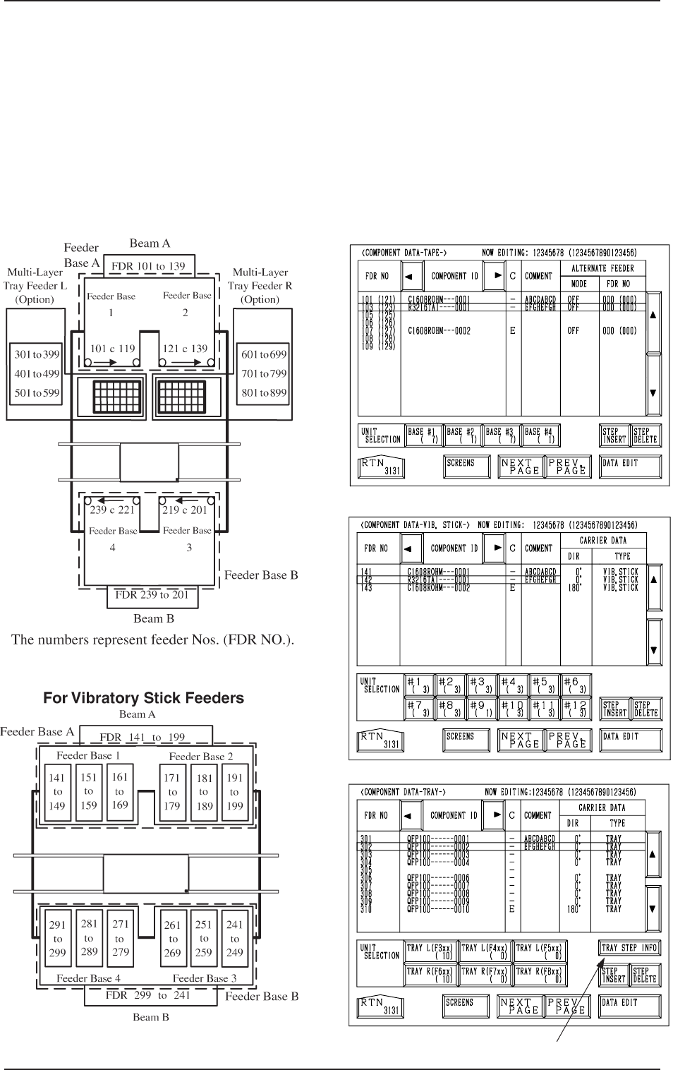
(1) When the [TAPE [A] (F101-F139)], the [VIB STICK [A] (F141-F199)],
or the [TRAY L (F301-F599)] key is pressed at the “PATTERN PRO-
GRAM EDIT” display, the corresponding display (Fig. 2B158, 2B159, or
2B160) appears on the screen.
When the [TAPE [B] (F201-F239)], the [VIB STICK B (F241-F299)], or
the [TRAY R (F601-F899)] key is pressed at the “PATTERN PROGRAM
EDIT” display, the corresponding display (similar to Fig. 2B158, 2B159, or
2B160) appears on the screen.
Fig. 2B158
[TAPE A]
[VIB. STICK A]
[TRAY L]
*1
Fig. 2B159
Fig. 2B160
Fig. 2B156
Fig. 2B157
For Tape Feeder
4.5 COMPONENT DATA Display
2-108
0305-001 Tg0858-PM-PM
4.5 COMPONENT DATA Display
(2) When the [DATA EDIT] key is pressed, the data edit display appears on
the screen.
• When the [TRAY STEP INFO] key *1 is pressed at the “COMPONENT
DATA-TRAY-” display, the “TRAY (L) STEPS INFORMATION” display
appears on the screen.
Refer to “4.5.3 Editing of Tray (L or R) Steps Information Data of Section
2” for details.
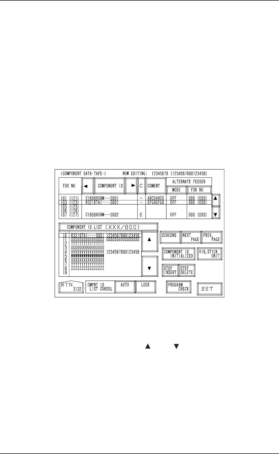
4.5.1 Editing of Component Data for Tape and Stick Feeders
The following example is based on the component data for Tape Feeder A.
As for Tape Feeder B and Vibratory Stick Feeders A and B, similar data edit
displays appear on the screen.
Operation Procedure
(1) When the [DATA EDIT] key is pressed at the “COMPONENT DATA”
display (Fig. 2B158), the following display appears on the screen.
Fig. 2B161
(2) Move the line cursor to the feeder No. (FDR NO) of the data to be edited.
(3) Press the [COMPONENT ID] key to enable the selection of component
IDs.
(4) Select a component ID with the [ ] or the [ ] key beside the “COMPO-
NENT ID LIST (XXX/800)” list box.
(5) Press the [SET] key. The selected component ID is set.
2-109