2OM-1011-002.pdf - 第30页
0305-001 Tg0858-PM-PM Fig. 2B9 Fig. 2B10 Fig. 2B1 1 First Page Second Page Third Page 2.3 OPERA TION DA T A Display When the [OPERA TION DA T A] key is pressed at the “P A TTERN PROGRAM EDIT” display , the following disp…
0305-001 Tg0858-PM-PM
2.2 PATTERN PROGRAM EDIT Display
When the “NAME (XX/XX)” key of the program data to be edited is selected
and the [PROGRAM EDIT] key is pressed at the “PATTERN PROGRAM”
display (Fig. 2B1), the following display appears on the screen.
From this display, the edit display for each pattern program data
can be opened.
*1
*4
*6
*5
*2
*3
*3
2.2 PATTERN PROGRAM EDIT Display
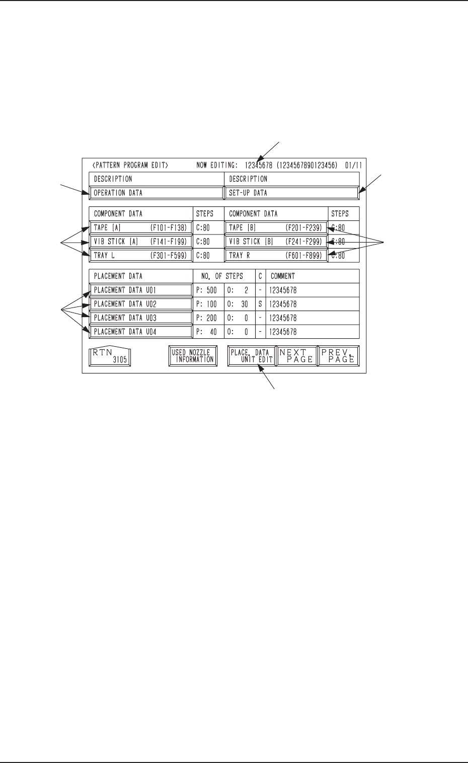
Fig. 2B8
*1 NOW EDITING: XXXXXXXX (XXXXXXXXXXXXXXXX)
Object Pattern Program Name and Comment 1 for Editing
*2 [OPERATION DATA] Key
Press this key to shift to the display for operation data editing.
*3 TAPE [A] (F101-F138), TAPE [B] (F201-F239),
VIB STICK [A] (F141-F199), VIB STICK [B] (F241-F299),
TRAY L (F301-F599), TRAY R (F601-F899)
Press one of the keys to open the desired display for editing the component
data related to each feeder.
*4 [PLACEMENT DATA UXX] Keys
Press one of the keys to open the desired display for editing the placement
data.
*5 [PLACE. DATA UNIT EDIT] Key
Press this key to open the display for delete, copy, or move operation of
blocked placement data (placement data divided into some blocks accord-
ing to U-Nos.).
*6 [SET-UP DATA] Key
Press this key to open the display for editing the set-up data.
2-10
0305-001 Tg0858-PM-PM
Fig. 2B9
Fig. 2B10
Fig. 2B11
First Page
Second Page
Third Page
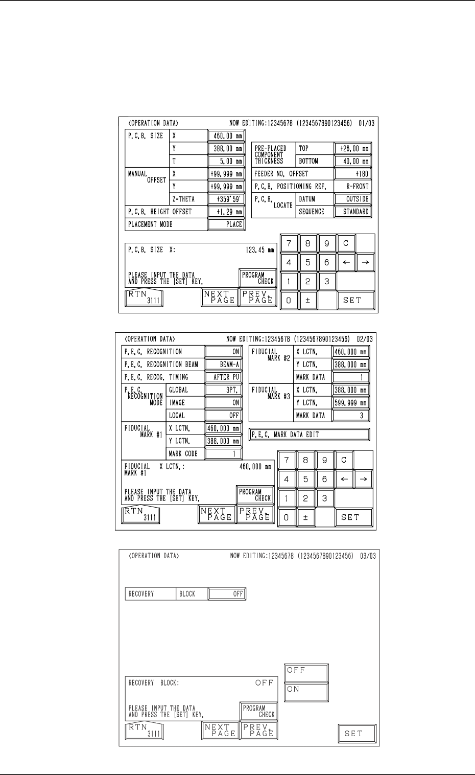
2.3 OPERATION DATA Display
When the [OPERATION DATA] key is pressed at the “PATTERN PROGRAM
EDIT” display, the following display appears on the screen.
Every time the [NEXT PAGE] or the [PREV. PAGE] key is pressed, another or
previous page appears on the screen.
2.3 OPERATION DATA Display
2-11
0305-001 Tg0858-PM-PM
2.3.1 Operation Data (Standard)
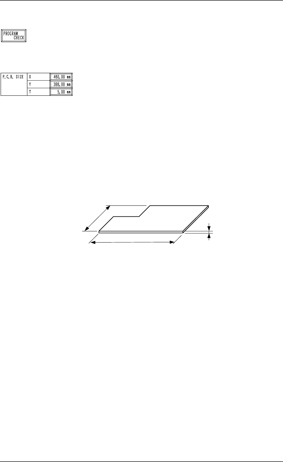
[PROGRAM CHECK] Key
When this key is pressed, the edited pattern program is checked.
First Page
P.C.B. SIZE
X (Horizontal), Y (Vertical)
Enter parameters (outmost dimensions) in the “X” and “Y”
data boxes. (Unit: mm)
Note: Be sure to set correct parameter in the “X” data box
because the set parameter is used to automatically cor-
rect the placement position when a parameter is se-
lected for the label “P.C.B. LOCATE MODE” at the
“P.C.B. TRANSFER MODE SET-UP” display.
The set parameter in the “Y” data box must be used as
a target width for the conveyor width automatic ad-
justment operation.
When a P.C.B. has a cutout, the dimensions shown
below represent each parameter.
Fig. 2B14
•
Data Input Range
X : 50.00 to 460.00 mm
Y : 50.00 to 381.00 mm
T (Thickness)
Set a parameter (thickness of P.C.B.) in the data box.
The set parameter must be used as a target value for the backup
table ascending position when a P.C.B. is clamped by the clamp
plates and positioned.
• Data Input Range: 0.30 to 5.00 mm
2-12
2.3 OPERATION DATA Display
P.C.B.
X
(
Horizontal
)
Y (Vertical)
T (Thickness)
Fig. 2B12
Fig. 2B13