2OM-1011-002.pdf - 第69页
0305-001 Tg0858-PM-PM 2-50 2.5.6 OFFSET X AUTO SETTING Display (Option) When the [OFFSET X AUTO SET] key is pressed at the “TRA Y (L) STEPS INFORMA TION” display (Fig. 2B95), the following display appears on the screen. …
0305-001 Tg0858-PM-PM2-49
2.5 COMPONENT DATA Display
2.5.5 TRAY OPERATION DATA Display (Option)
When the [TRAY (L) OPN DATA] key is pressed at the “TRAY (L) STEPS
INFORMATION” display (Fig. 2B95), the following display appears on the
screen.
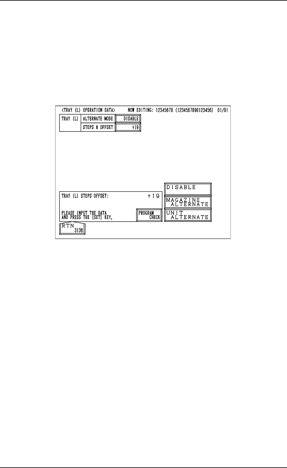
While the tray L information is being edited, the “TRAY (L) OPERATION
DATA” display appears on the screen.
While the tray R information is being edited, the “TRAY (R) OPERATION
DATA” display appears on the screen.
Fig.2B101
MAGAZINE ALTN
“ENABLE” or “DISABLE”can be set in the data box to determine whether
or not the magazine alternate function should be used.
[MAGAZINE ALTERNATE] :
The magazine alternate function becomes valid.
[UNIT ALTERNATE] :
The unit alternate function becomes valid.
About the magazine alternation function
When this function is used, components can be supplied during automatic
operation without stopping the machine.
STEPS # OFFSET
The steps # offset value can be entered in the data box.
Steps # Offset
This offset data is used to shift the current feeder (currently allocated com-
ponents) to the multi-layer tray feeder.
Based on the FDR No. and the component data indicated in the placement
data, the current feeder position is shifted as much as this offset.
0305-001 Tg0858-PM-PM2-50
2.5.6 OFFSET X AUTO SETTING Display (Option)
When the [OFFSET X AUTO SET] key is pressed at the “TRAY (L) STEPS
INFORMATION” display (Fig. 2B95), the following display appears on the
screen.
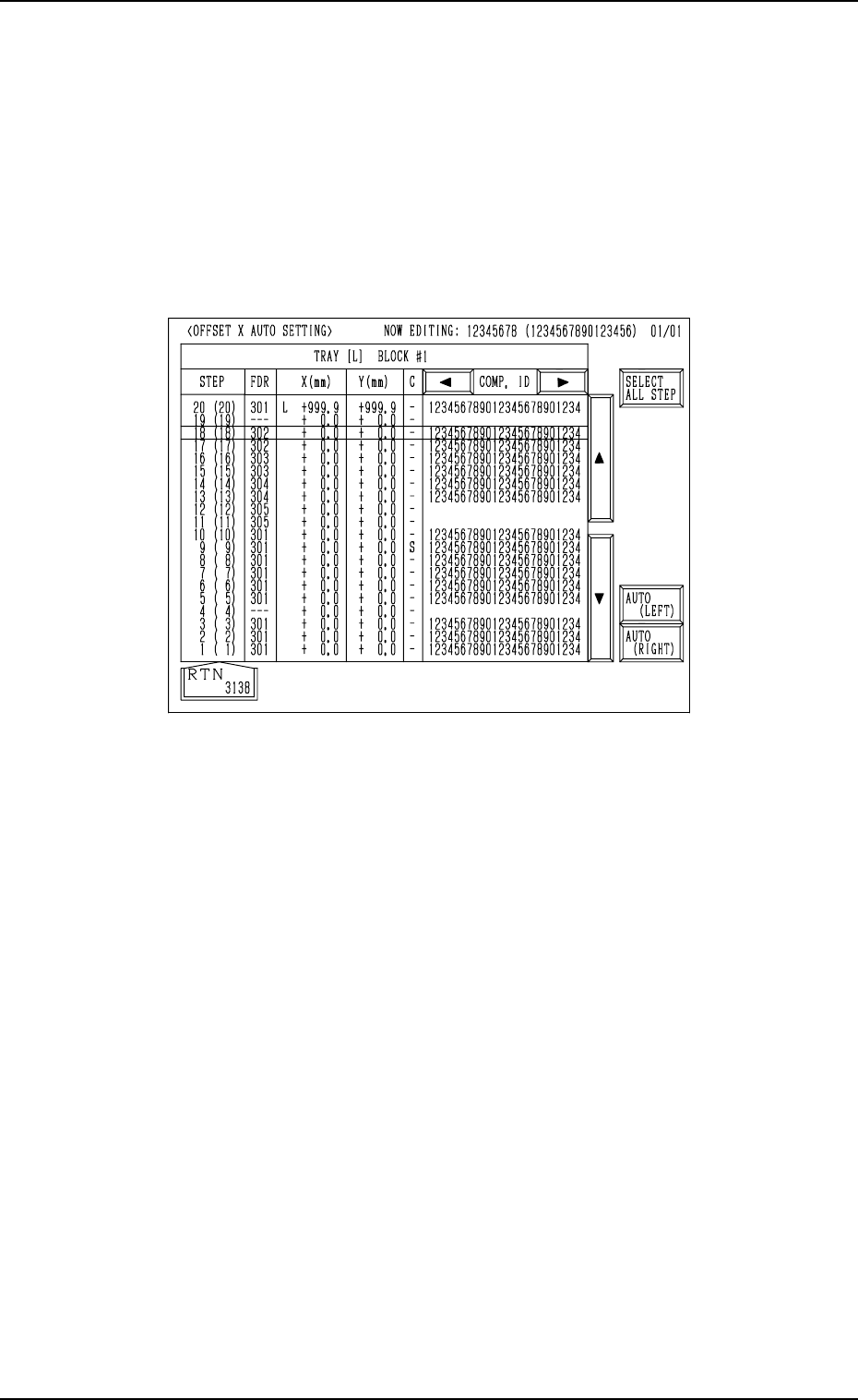
While the tray L information is being edited, “OFFSET X AUTO SETTING”
display for Tray L appears on the screen.
While the tray R information is being edited, “OFFSET X AUTO SETTING”
display for Tray R appears on the screen.
2.5 COMPONENT DATA Display
Fig. 2B102
As the values for the tray position offset “X (mm)” change depending on whether
or not “AUTO (LEFT)” or “AUTO (RIGHT)” is set for the tray in each step
(the tray to be specified as a multi-layer tray), it is required to set the offset
values for each individual trays.
That is, the offset values X (design values) can be set by selecting either the
[AUTO (LEFT)] or the [AUTO (RIGHT)] key.
When the [SELECT ALL STEP] key is pressed, the offset values X in all steps
can be entered automatically.
0305-001 Tg0858-PM-PM
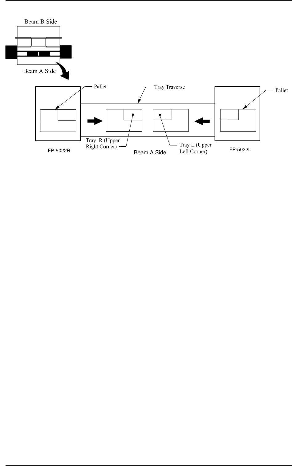
[AUTO (LEFT)] and [AUTO (RIGHT)] Keys:
“LEFT” or “RIGHT” represents the direction in which a tray
should be pushed when it is set on the pallet.
Any wasteful motion can be suppressed when Tray R is set at
the upper right corner of the pallet and Tray L at the upper left
corner as shown in the following figure.
2-51
2.5 COMPONENT DATA Display
Fig. 2B103