4H4CEOM1.pdf - 第105页
Page 3-27 FUNCTIONS 3 3-5 Machine Settings This is used to set the state of machine that does not depend on production data. ∗ On the main menu (default state) in the operator mode, you cannot select this function. 1. Pr…
Page 3-26
Machine Adjustment
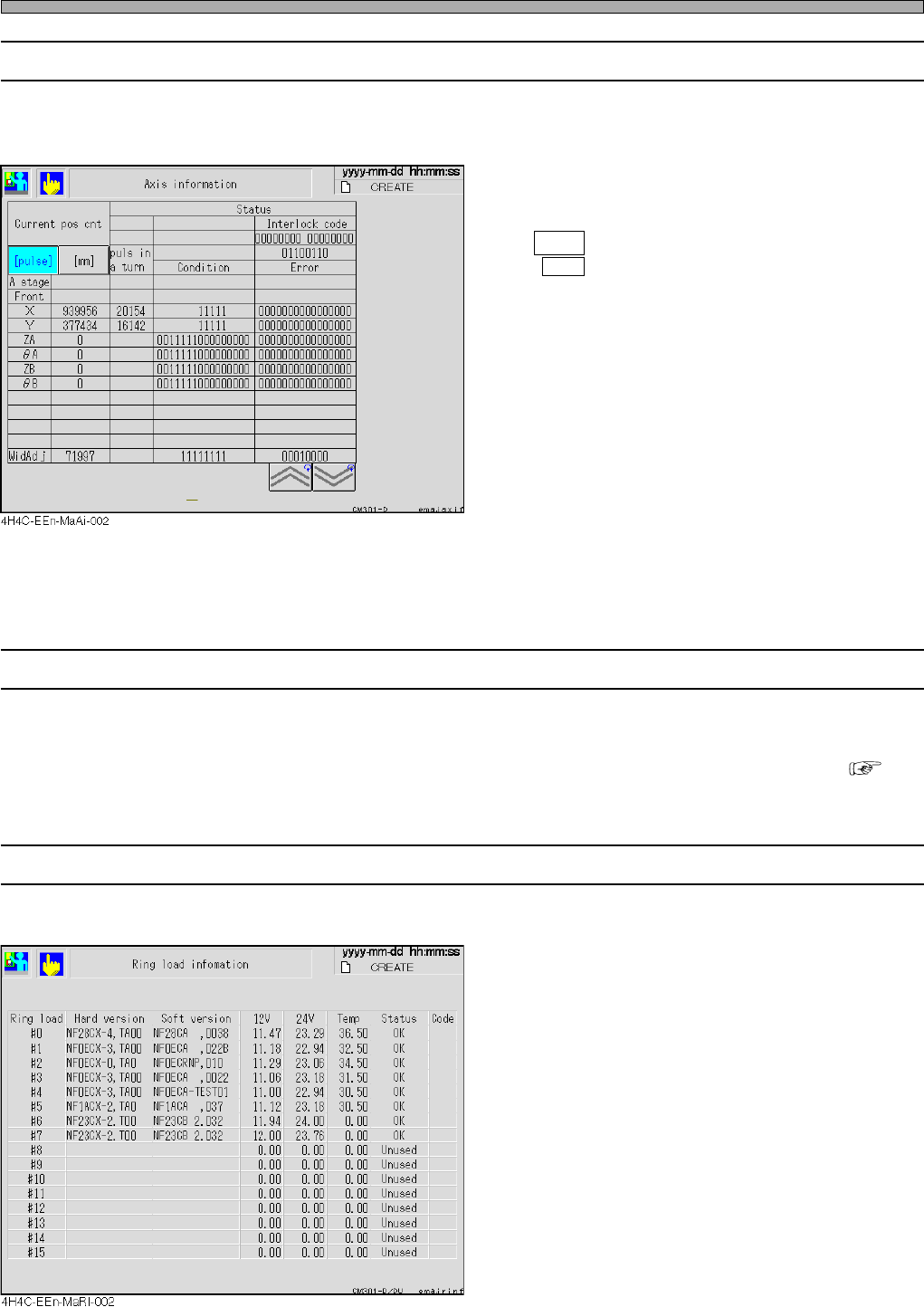
3-4-9 Axis Information
This is used to check the current positions of all the axes the machine controls and the status
information.
Current pos cnt
Displays the current position of each axis in
mm or pulse of status address.
pulse : Displays the current position in pulse.
mm : Displays the current position in mm.
Status
Displays the state of status address, error/puls
in a turn of each axis, in bit.
Pulse in a turn
This data is sampled and displayed against X-
and Y-axes only.
<Meaning of abbreviation>
X : X-axis of X-Y unit
Y : Y-axis of X-Y unit
ZA : ZA-axis
θ
A:
θ
A-axis
ZB : ZB-axis
θ
B:
θ
B-axis
3-4-10 Recognition Device Maintenance
This is used to check all the recognition processing motions.
∗ For information about how to operate it, refer to “Appendix A RECOGNITION DEVICE” ( A-5
Recognition Device Maintenance).
3-4-11 Ring Load Information
This is used to display the load onto ring.
4H4C-E-OMA03-A01-03
Page 3-27
FUNCTIONS
3
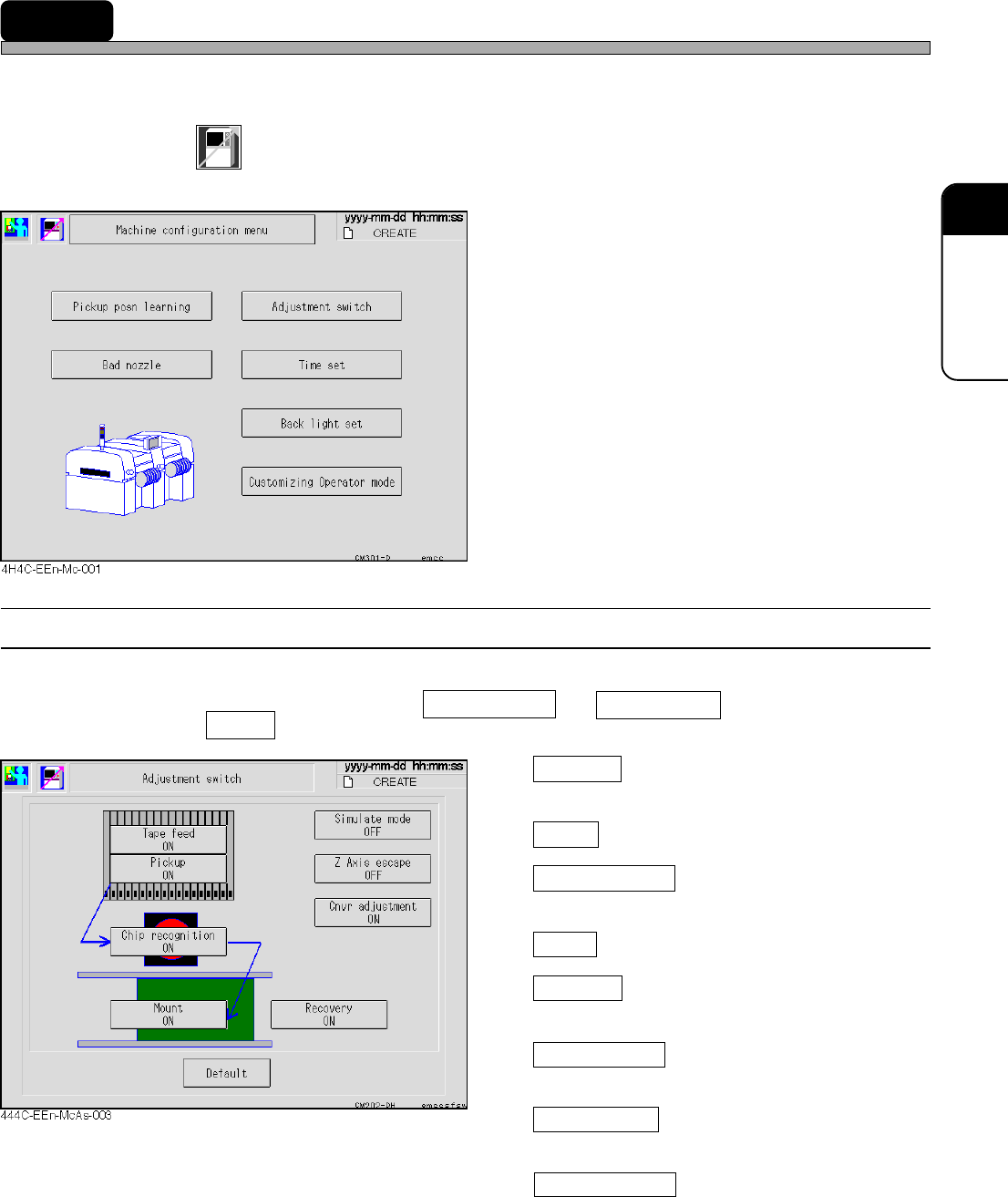
3-5 Machine Settings
This is used to set the state of machine that does not depend on production data.
∗ On the main menu (default state) in the operator mode, you cannot select this function.
1. Press
Machine
config
on the main menu.
•“Machine configuration menu” is displayed.
∗ Pressing a switch displays each setting screen.
3-5-1 Switches for Adjustment
You can change the conditions of production motion for adjustment temporarily.
Usually, all the items are ON except Simulate mode and Z Axis escape .
Pressing Default or restarting the machine returns the settings to the usual ones.
Tape feed
When it is ON, tape feeding by the feeder is
enabled.
Pickup
When it is ON, pick-up motion is enabled.
Chip recognition
When it is ON, chip recognition and error check
is enabled.
Mount
When it is ON, mounting motion is enabled.
Recovery
When it is ON, re-pickup of the pick-up error
and recognition error chips is enabled.
Simulate mode
When it is ON, the repeated operation of
production data is enabled.
Z Axis escape
When it is ON, the operation with Z-axis
retracted at the fixed height is enabled.
When it is ON, a width adjustment is made.
When it is OFF, a width adjustment is not
made.
4H4C-E-OMA03-A01-03
Cnvr adjustmen
Page 3-28
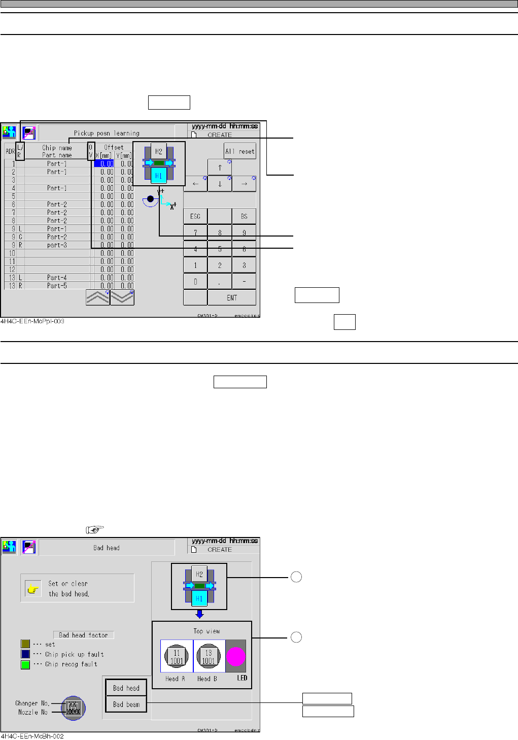
3-5-2 Pick-up Position Learning
This is used to check the correction value through the pick-up position learning during production
for each feeder address.
For the learning data, during production, 1/10 of the recognition result will be added on to the
current learning value.
When you press All reset or load production data, the pick-up position learning data of all the
feeder addresses are reset to 0.0.
• The “Chip name” or “Parts name” for each tape
feeder is displayed. (Every time you press this,
they are changed.)
• As for the vibratory stick feeder, L, C or R are
displayed.
• Choose the feeder table to be displayed.
• OV : This field lights up in yellow when the
pick-up learning position exceeds the
limit.
All reset
Deletes all the learning data.
Press Yes when the message appears.
3-5-3 Defective Head
∗ This screen is displayed when Bad nozzle is pressed on the “Machine configuration menu” screen.
This is used to check the state of the head and specify/reset the defective head.
The button of the head which has become defective automatically during production is colored
according to the factor.
• The defective head will not be used for production. When canceling it after checking, press the
button of the head you would like to cancel. Then the color of the button returns to a normal color
(light gray).
• When you would like to specify a normal nozzle as a defective one, press the button of the head
you would like to specify defective. Its button will be colored in yellow (specified defective head
color).
• During an automatic operation, you cannot specify and cancel defective head.
• At the judgment value screen, set the conditions for the automatic defective head setting.
( Maintenance Manual)
Choose the stage that has the head you will
specify or cancel.
Press the switch of the head you would like to
specify defective or cancel.
Every time you press the switch, “specify” and
“cancel” are changed over.
Bad head : Specifies by the head.
Bad beam : Specifies by the head.
Machine Settings
1
2
4H4C-E-OMA03-A01-04
L :Left
C:Center
R:Right