4H4CEOM1.pdf - 第48页
Page 1-4 Status indicator (3-color indicator light) This light indicates the state of machine. If any trouble occurs during operation, it warns you by a buzzer . Regulator Knob Used to adjust the supply air pressure. Nam…
Page 1-3
GENERAL DESCRIPTION
1
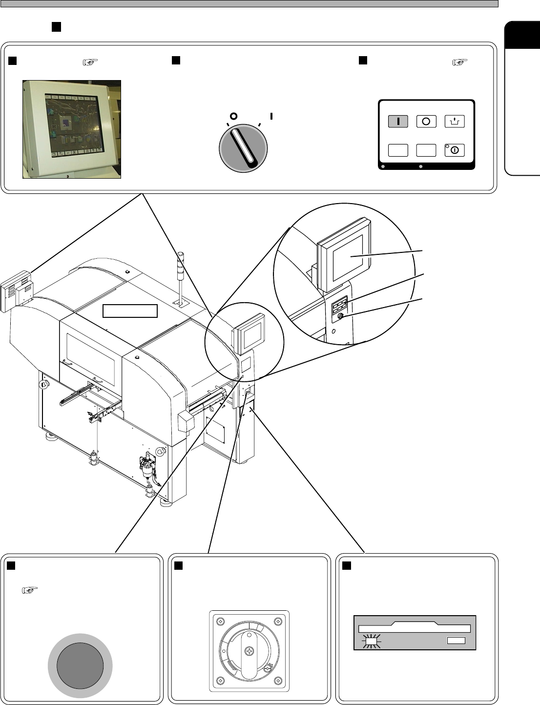
Servo Switch
Used for ON/OFF power
switch of servo system motor.
Operating Units
Touch Panel ( 2-2)
Used to operate the machine.
Emergency Stop Button
(Two in All)
( SAFETY PRECAUTIONS)
When you press this button, the
machine comes to an emergent
stop.
Names and Mechanism of Each Unit
(Inside the cover)
443C-101P
Operating Panel ( 2-1)
Used to start/stop the
machine and so on.
Floppy Disk Drive
Used to write and read pro-
gramming data.
Power Supply Switch
Used for ON/OFF power switch
of machine.
OFF ( )
ON ( )
SERVO
443C-101P
STOP
UNLOCK
STEP
START
LIGHT ON
SELECT
KEY LOCK
KEY LOCK
BACK LIGHT OFF
BACK LIGHT OFF
E
M
E
R
G
E
N
C
Y
S
T
O
P
R
E
L
E
A
S
E
T
R
I
P
O
F
F
O
N
R
E
S
E
T
Front View
4H4C-AA01
4H4C-E-OMA01-A01-00
Touch Panel
Operating Panel
Servo Switch
4H4C-001E
Page 1-4
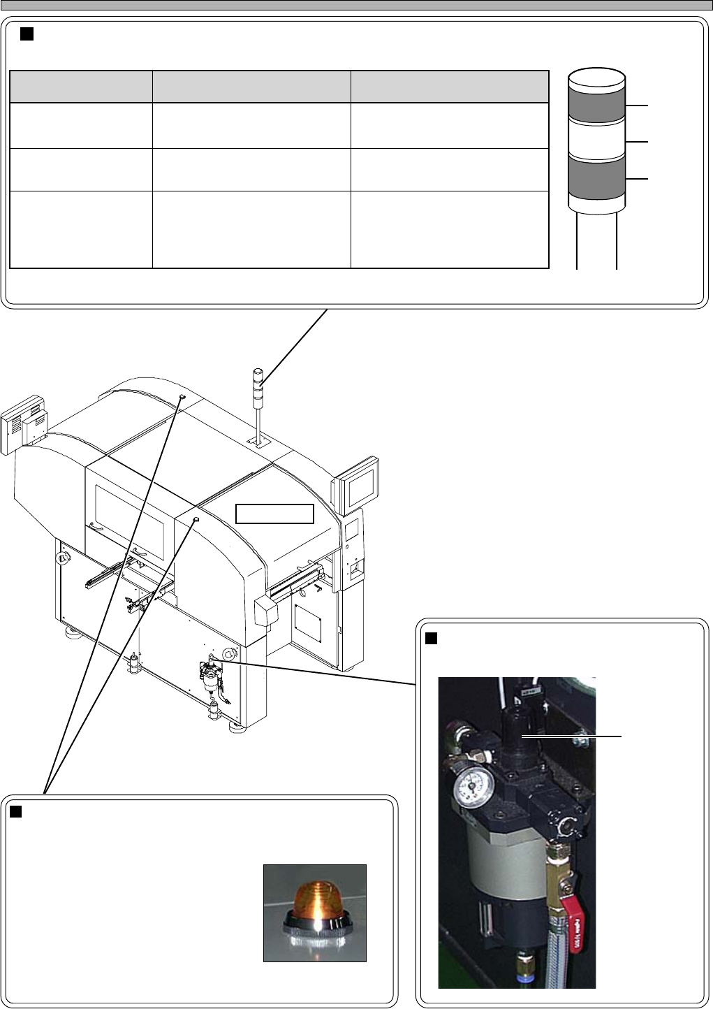
Status indicator (3-color indicator light)
This light indicates the state of machine. If any trouble occurs during operation, it warns you by a buzzer.
Regulator Knob
Used to adjust the supply air pressure.
Names and Mechanism of Each Unit
Stage Lamp (Two in All)
When chips run out or trouble occurs on a stage, its lamp
blinks.
During automatic operation
• Not lit : Running normally
• Lit : Out of chips
• Blinking: Trouble
During teaching
• Lit : Running
444C-109TE
Front View
Red
Yellow
Green
4H4C-001P
Regulator
knob
444C-101P
4H4C-AA01
ecnaraeppA/roloC gninaeM esuaC
tiL/neerG
ronoitarepocitamotuagniruD
gninnurtnemtsujdaenihcam
yllamrongninnuR
gniknilB/wolleY
hcihw,gninrawroelbuorT
noitarepoeunitnocnacuoy
potselcyC/etaidemmI
slairetamfotuO
gniknilB/deR
tonnacuoyhcihw,elbuorT
noitarepoeunitnoc
)potsycnegremE(
potsycnegremE•
.cte,rotomfoelbuort,tfahS•
erusserprianiporD•
elbuorttropsnartdraoB•
4H4C-E-OMA01-A01-00
Page 1-5
GENERAL DESCRIPTION
1
Names and Mechanism of Each Unit
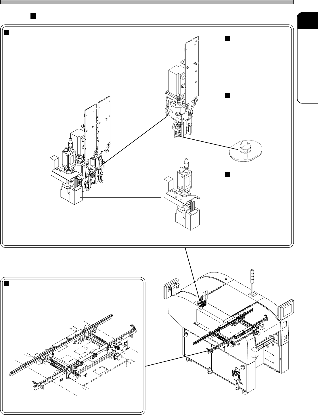
Main Units
Head Unit (Two in All)
Consists of a head camera and two transfer heads.
Board Conveyor
Transports boards in and out.
010WC0AA01
4H4C-018E
160JC0AA01
030CC0AA01
4H4C-E-OMA01-A01-00
Transfer Head
Picks up chips and
mounts them onto the
board. Each head unit
has two transfer
heads.
Nozzle
Picks up chips using a
vacuum pressure.
Various sizes and
shapes of nozzles
support various chips.
Head Camera
Used for board recog-
nition, thermal correc-
tion and calibration.
444C-405E
4H4C-AI00