4H4CEOM1.pdf - 第49页
Page 1-5 GENERAL DESCRIPTION 1 Names and Mechanism of Each Unit Main Units Head Unit (T wo in All) Consists of a head camera and two transfer heads. Board Conveyor T ransports boards in and out. 010WC0AA01 4H4C-018E 160J…
Page 1-4
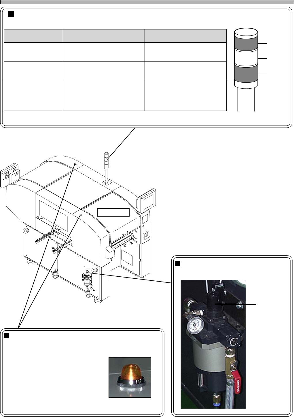
Status indicator (3-color indicator light)
This light indicates the state of machine. If any trouble occurs during operation, it warns you by a buzzer.
Regulator Knob
Used to adjust the supply air pressure.
Names and Mechanism of Each Unit
Stage Lamp (Two in All)
When chips run out or trouble occurs on a stage, its lamp
blinks.
During automatic operation
• Not lit : Running normally
• Lit : Out of chips
• Blinking: Trouble
During teaching
• Lit : Running
444C-109TE
Front View
Red
Yellow
Green
4H4C-001P
Regulator
knob
444C-101P
4H4C-AA01
ecnaraeppA/roloC gninaeM esuaC
tiL/neerG
ronoitarepocitamotuagniruD
gninnurtnemtsujdaenihcam
yllamrongninnuR
gniknilB/wolleY
hcihw,gninrawroelbuorT
noitarepoeunitnocnacuoy
potselcyC/etaidemmI
slairetamfotuO
gniknilB/deR
tonnacuoyhcihw,elbuorT
noitarepoeunitnoc
)potsycnegremE(
potsycnegremE•
.cte,rotomfoelbuort,tfahS•
erusserprianiporD•
elbuorttropsnartdraoB•
4H4C-E-OMA01-A01-00
Page 1-5
GENERAL DESCRIPTION
1
Names and Mechanism of Each Unit
Main Units
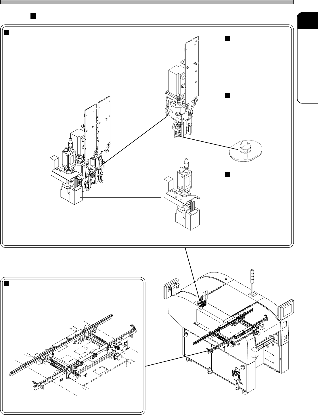
Head Unit (Two in All)
Consists of a head camera and two transfer heads.
Board Conveyor
Transports boards in and out.
010WC0AA01
4H4C-018E
160JC0AA01
030CC0AA01
4H4C-E-OMA01-A01-00
Transfer Head
Picks up chips and
mounts them onto the
board. Each head unit
has two transfer
heads.
Nozzle
Picks up chips using a
vacuum pressure.
Various sizes and
shapes of nozzles
support various chips.
Head Camera
Used for board recog-
nition, thermal correc-
tion and calibration.
444C-405E
4H4C-AI00
Page 1-6
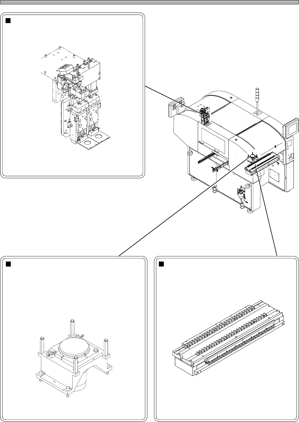
Z Unit
Moves the head unit upward and downward.
Names and Mechanism of Each Unit
Line Camera (Two in All)
Used to recognize chips.
This can recognize all the chips from minute ones
to large-sized and unusual-shaped ones.
010VC0AA01
4H4C-AJ00
160KC0AA00
4H4C-016E
4H4C-E-OMA01-A01-01
Tape Feeder Table
This is composed of the table, where the tape
feeders are set, and the tape feeding part, which
drives feeders.
∗ The tape feeding part operates even if the
vibratory stick feeder is used; however this is not
out of order.