4H4CEOM1.pdf - 第66页
Page 2-2 h c t i w S n o i t c n u F . p o t s y r a r o p m e t a r e t f a t i e m u s e r o t d n a n o i t c u d o r p t r a t s o t d e s U . t u o g n i t n i r p p o t s d n a ) p o t s e t a i d e m m I ( y l i r…
Page 2-1
Basic Operation
This chapter describes the basic operation. This includes how to operate the operat-
ing panel, touch panel and the functions.
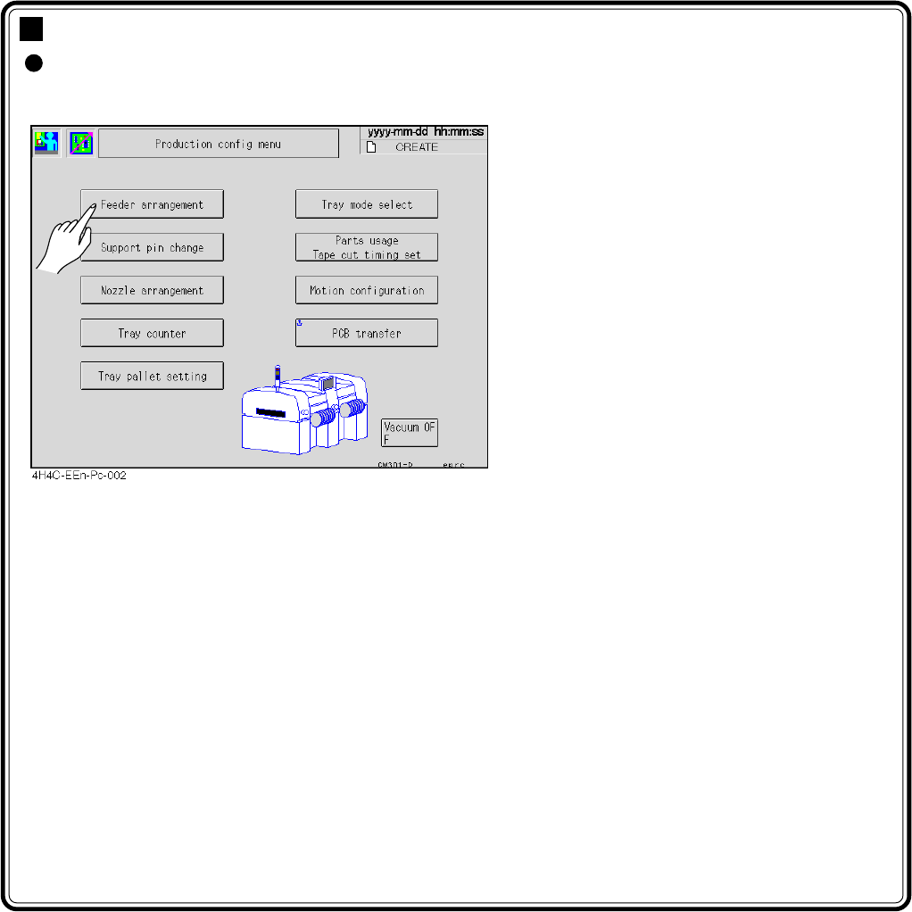
You can choose an item by pressing its icon
or button on the screen.
4H4C-E-OMA02-A01-02
Chapter 2
BASIC OPERATION
Page 2-2
hctiwS noitcnuF
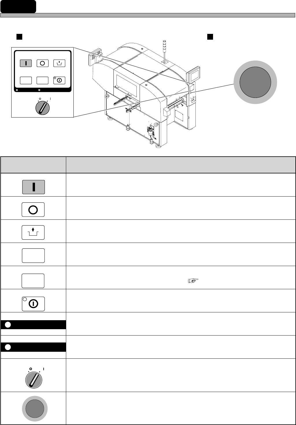
.potsyraropmetaretfatiemuserotdnanoitcudorptratsotdesU
.tuognitnirppotsdna)potsetaidemmI(yliraropmetnoitcudorppotsotdesU
.noitneverpregnadrofhctiwssihthtiwdesueraenihcamehtkrowotsehctiwsehT
.potsyraropmetamorfnoitompetsehtrofdesU
.lenaphcuotfothgilkcabehtnonrutotdesU
)thgilkcaBgnitteS5-5-3(.yllanoitpotesebnacemitffo-thgilkcabehT•
hcuotdnalenapgnitarepoehtesuuoynehwedisraerrotnorfehtesoohcotdesU
).elbareposemocebedissihtdnasthgilpmaleht,dehsupsitinehW(.lenap
.cte,FFOOVRESotgniwodilavnisilenapgnitarepofoesuehtnehwsthgilpmalehT
.sthgilpmalsiht,ffosnrutlenaphcuotfothgilkcabehtelihW
)hctiwsovres(OVRES
trapelibomehtotnisdnahruoytresniuoynehW.rotomehtrofhctiwsrewopasisihT
htobNOnrut,noitcudorptratsuoynehW.hctiwssihtFFOnrutoteruseb,enihcamfo
.slenapraerdnatnorfnosehctiwsovres
)nottubpotsycnegreme(POTSYCNEGREME
tillup,teseroT.potstnegremenaotsemocenihcameht,nottubsihtsserpuoynehW
.drawrof
4H4C-E-OMA02-A01-00
2-1 Operating Panel
This section describes the operational areas of the machine and its basic operation.
START
STOP
UNLOCK
E
M
E
R
G
E
N
C
Y
S
T
O
P
OFF ( )
ON ( )
SERVO
SELECT
E
M
E
R
G
E
N
C
Y
S
T
O
P
KEY LOCK
OFF ( )
ON ( )
SERVO
STOP
UNLOCK
STEP
START
LIGHT ON
SELECT
KEY LOCK BACK LIGHT OFF
4H4C-006TE
Operating Panel Emergency Stop Button
(Two in All)
STEP
BACK LIGHT OFF
LIGHT ON
4H4C-AA01
( 3-5-5 Setting Backlight)
Page 2-3
BASIC OPERATION
2
F 1F 2F 3F 4F 5F 6F 7F 8
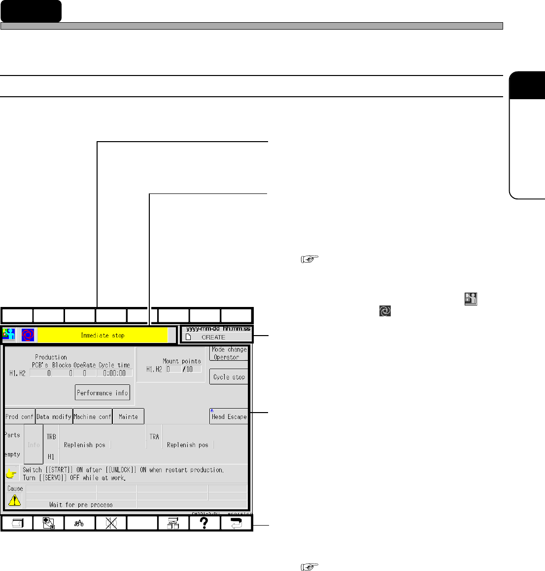
2-2 Touch Panel
This machine is operated by using the touch panel and operating panel. This section describes the
basic operation of touch panel.
2-2-1 Touch Panel Configuration
Touch panel configuration is as follows.
a) Upper Function Keys
These are currently not used. They perform no
function if pressed.
b) Hierarchy, Mode and Menu Name
Display Area
The state of current displayed screen is
displayed by the icon and the item name. This
is the same icon as appears in the Main Menu.
( 2-3 Main Menu)
e.g.) The screen as shown left
This shows this machine has come to an
immediate stop in the engineer mode ( )
during production ( ).
c) Date, Time and Data Name Display
Area
Present date, time and data name are dis-
played.
d) State Display, Switches and Mes-
sages Area
The state of this machine, messages, the
switches for operation and so on are displayed.
e) Lower Function Keys
These are allotted the functions to be used
frequently.
( 2-2-2 Function Keys)
4H4C-E-OMA02-A01-04
4H4C-EEn-PrSs-005