4H4CEOM1.pdf - 第93页
Page 3-15 FUNCTIONS 3 Production Settings 4H4C-E-OMA03-A01-03 However , when both-side mounting is set to “Use (1)” at the option configuration screen as shown left, the motion configuration screen no longer displays thi…
Page 3-14
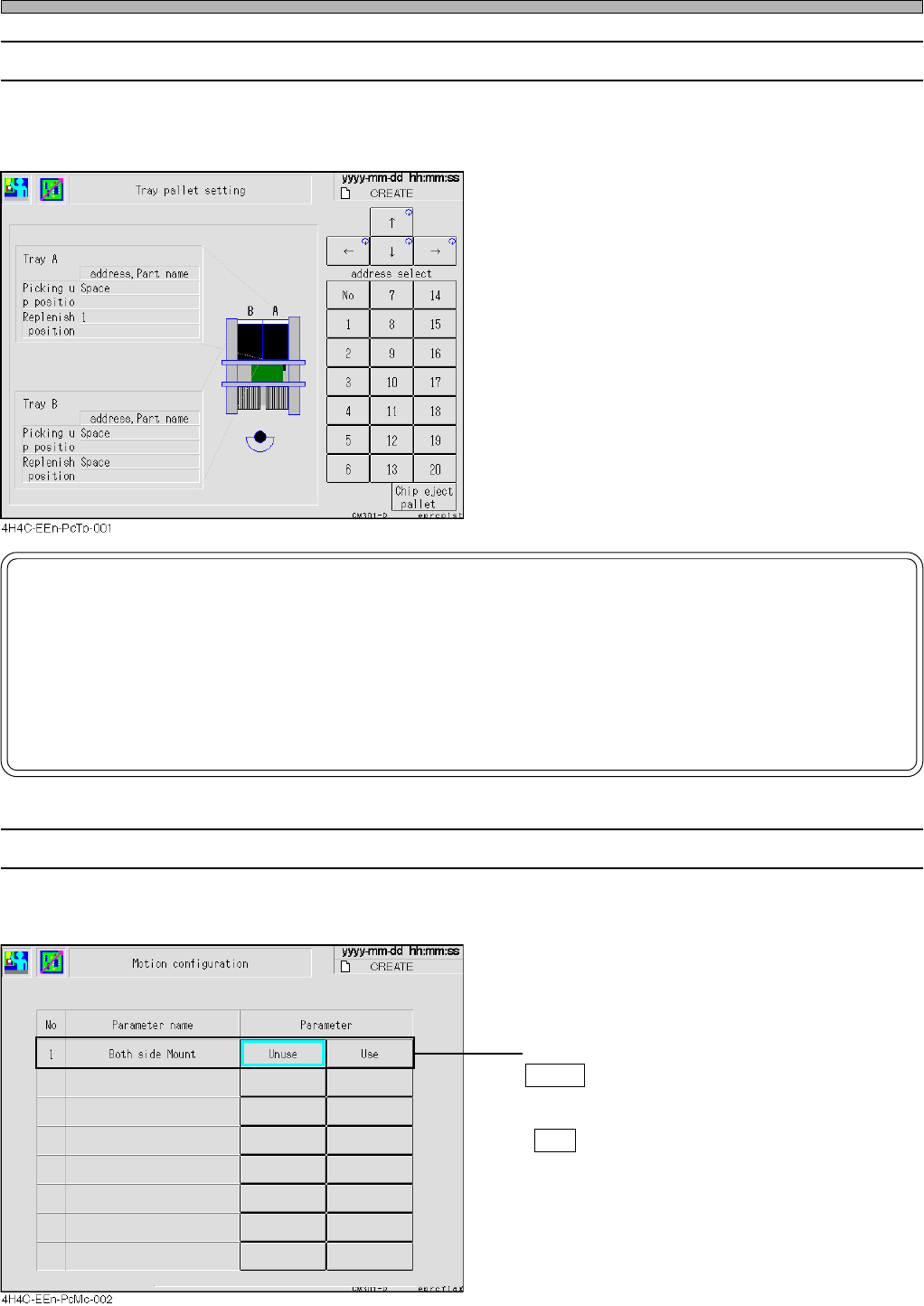
3-2-8 Tray Pallet Setup
The address of the pallet drawn out to the pick-up position and the address of the pallet drawn out
to the supply position are displayed each.
NOTICE
If you input tray pallet setup incorrectly by hand, the tray feeder will be damaged.
So be careful.
For example, if you change the setup to 6 though a pallet of the address 8 is actually drawn out, the
machine puts the pallet back to the address 6 when an operation resumed. However, the pallet of the
address 6 has been at the address 6, so the pallets collide with each other. If worst comes to worst, the
tray feeder itself will be damaged.
4H4C-E-OMA03-A01-02
Production Settings
3-2-9 Motion Setup
This part describes how to set up the machine’s motion.
• Both side Mount
Unuse : When mounting is complete, board
transport starts the moment the support
pins starts to lower.
Use : Board transport starts after the support
pins have been lowered.
Page 3-15
FUNCTIONS
3
Production Settings
4H4C-E-OMA03-A01-03
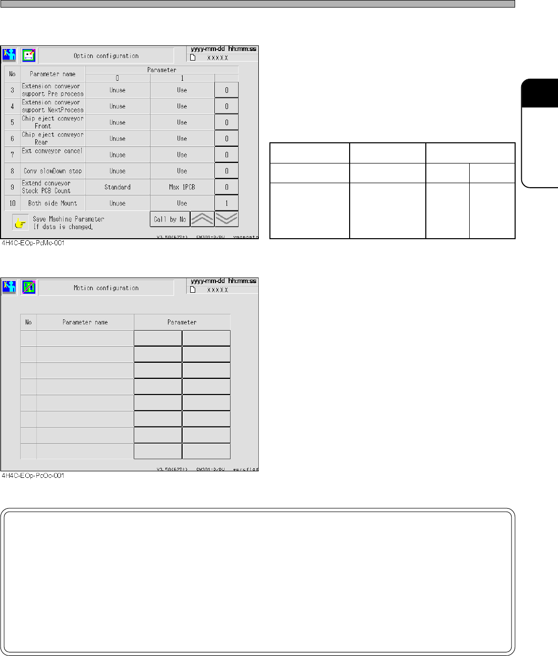
However, when both-side mounting is set to
“Use (1)” at the option configuration screen as
shown left, the motion configuration screen no
longer displays this item.
Option configuration Enabled Disabled
Motion configuration The item is hidden Enabled Disabled
Transport operation
Both-side
mounting
is Disabled
Both-side
mounting
is enabled
Both-side
mounting
is enabled
NOTICE
By default, OFF is selected.
This data will not be changed unless a user changes this setting.
When mounting the board whose reverse side has been mounted, be sure to set
“Both side Mount” to “Use”.
If it is set to “Unuse”, the chips on the reverse side may collide with the support
pins.
Page 3-16
3-3 Production Information
The running states of production board, pick-up, chip feeding unit, etc. are displayed.
1. Press
Performance
info
on the main menu.
• The running information screen is displayed.
∗ Pressing an information switch displays each
information screen.
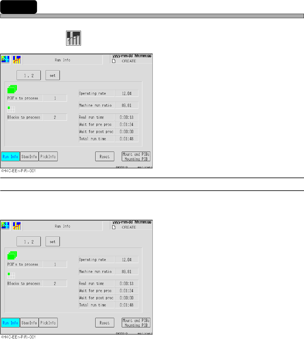
3-3-1 Run Information
The count of produced boards and blocks, each running time, etc. are displayed for each stage.
• Without reset, data will be added on irrespective of switchover of board types.
PCB’s to process
The number of the boards passed through the
specified stage
[The number of mounted boards + The number
of boards just passed through]
Blocks to process
The number of blocks produced (mounted)
actually.
Operating rate
Rate of the time when the machine is actually
working for mounting during the production
mode
[Real run time / Total run time]
Machine run ratio
Running rate of the specified stage alone
adding Wait for proc time to Real run time
[(Real run time + Wait for proc time) / Total run
time]
Real run time
The time found by subtracting the mounting
stop time due to errors, wait for the previous
and next processes and so on from the time
during the production mode
[Total run time - Total down time]
Wait for pre proc
The time waiting for the previous process to be
prepared
Wait for post proc
The time waiting for the next process to be
prepared
Total run time
The time during the production mode
4H4C-E-OMA03-A01-01