4H4CEOM1.pdf - 第92页
Page 3-14 3-2-8 T ray Pallet Setup The address of the pallet drawn out to the pick-up position and the address of the pallet drawn out to the supply position are displayed each. NOTICE If you input tray pallet setup inco…
Page 3-13
FUNCTIONS
3
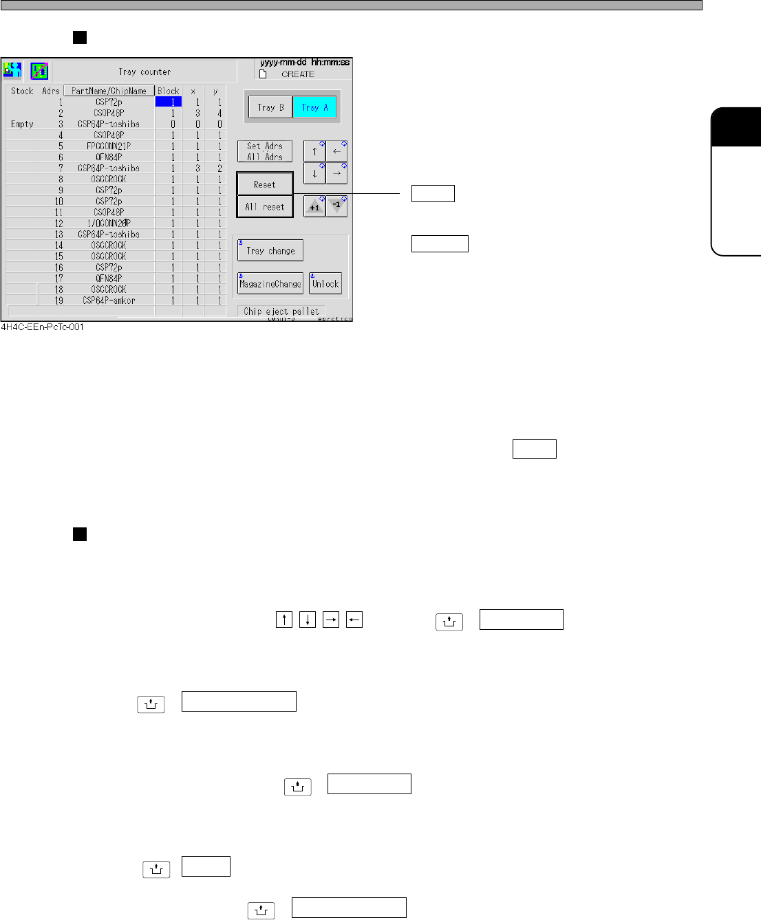
Reset/All Reset
• Reset
Sets the pick-up start position of the address
pointed by a cursor to (X = 1 , Y = 1).
All reset
Sets all addresses to (X = 1 , Y = 1).
∗ Also the defective chip eject pallet will be reset
to the initial position.
Resetting the defective chip eject pallet
Once a defective chip is ejected on some position, the next one is ejected on the next position
because the machine memorizes the position where the chip has already been ejected so that this
chip will not be piled on that chip.
After removing the chips on the pallet, press “Chip eject pallet” then Reset to delete this memory.
Next time, the chip are ejected on from the first position onward again.
Changing Parts
a) Changing Tray
Draws out the specified tray pallet to the supply position.
Select the desired tray using , and press
UNLOCK
+ Tray change .
b) Changing Magazine
Used when changing tray magazines.
Press
UNLOCK
+ MagazineChange .
c) Changing Defective Chip Eject Pallets
Draws out the defective chip eject pallet to the supply position.
Press “Chip eject pallet” then
UNLOCK
+ Tray change .
d) Unlocking Magazine Door
Unlocks the magazine door.
Press
UNLOCK
+ Unlock .
∗ If each axis of the tray is not at the magazine changeable position, the door can not be unlocked.
In such a case, press
UNLOCK
+ MagazineChange first .
Production Settings
4H4C-E-OMA03-A01-01
Page 3-14
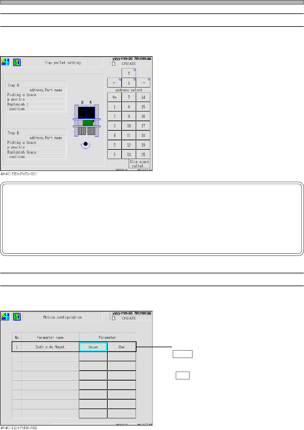
3-2-8 Tray Pallet Setup
The address of the pallet drawn out to the pick-up position and the address of the pallet drawn out
to the supply position are displayed each.
NOTICE
If you input tray pallet setup incorrectly by hand, the tray feeder will be damaged.
So be careful.
For example, if you change the setup to 6 though a pallet of the address 8 is actually drawn out, the
machine puts the pallet back to the address 6 when an operation resumed. However, the pallet of the
address 6 has been at the address 6, so the pallets collide with each other. If worst comes to worst, the
tray feeder itself will be damaged.
4H4C-E-OMA03-A01-02
Production Settings
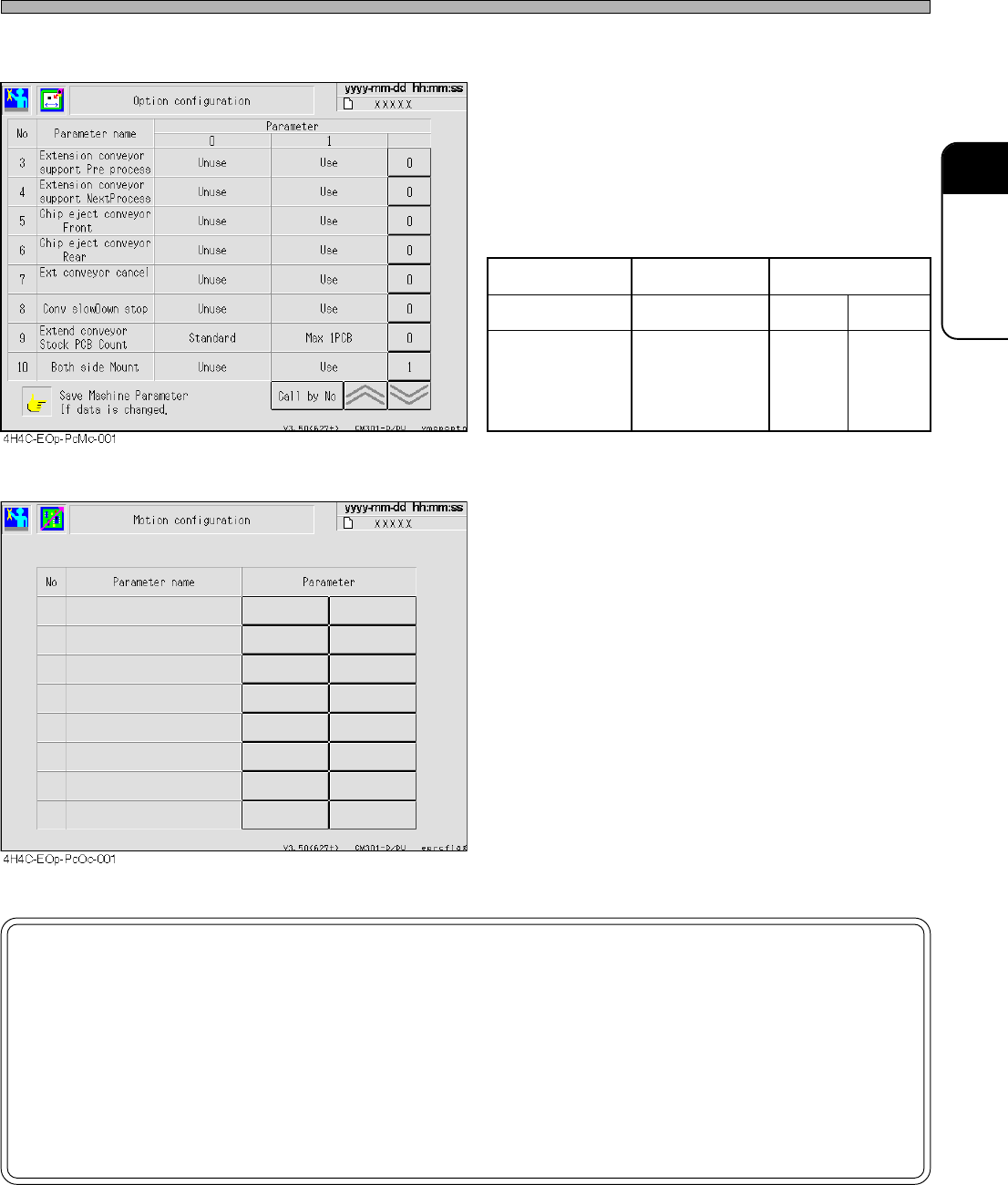
3-2-9 Motion Setup
This part describes how to set up the machine’s motion.
• Both side Mount
Unuse : When mounting is complete, board
transport starts the moment the support
pins starts to lower.
Use : Board transport starts after the support
pins have been lowered.
Page 3-15
FUNCTIONS
3
Production Settings
4H4C-E-OMA03-A01-03
However, when both-side mounting is set to
“Use (1)” at the option configuration screen as
shown left, the motion configuration screen no
longer displays this item.
Option configuration Enabled Disabled
Motion configuration The item is hidden Enabled Disabled
Transport operation
Both-side
mounting
is Disabled
Both-side
mounting
is enabled
Both-side
mounting
is enabled
NOTICE
By default, OFF is selected.
This data will not be changed unless a user changes this setting.
When mounting the board whose reverse side has been mounted, be sure to set
“Both side Mount” to “Use”.
If it is set to “Unuse”, the chips on the reverse side may collide with the support
pins.