00193631-0602.pdf - 第13页
Adjustment Instructions MTC 2 3 Construction and mode of operation 12/2007 Edition 13 3 Construction and mode of operation The MTC 2 extends the cap acity of a SIPLACE st ation to supply components by up to 100 JEDEC waf…
2 Operational safety Adjustment Instructions MTC 2
12/2007 Edition
12
WARNING
It is absolutely necessary to adhere to the sequence of the individual setup activities to prevent
injury and/or material damage.
Do not operate the MTC 2 outside the SIPLACE station.
Danger of hands becoming crushed in the drive area of the lifting and feed axes and in the travel
range of the WTCs.
Ensure that each time the MTC 2 is started, all screws that have been loosened are secured using
Loctite 222 (exception: screws with lock nuts).
All grounding connections to the covers which have been removed must be reattached.
WARNING
Before carrying out work on the motors of the lifting axes, you must ensure that the lifting axis is
moved to the lowest position so that it can be rested against the buffer. Otherwise the lifting axis
may drop a significant distance when the motor brakes are put out of action.
There is a risk of injury and/or damage to machinery if these instructions are not followed.
DANGER
Some of these activities require access to parts of the machine which carry dangerous levels of
voltage, or which move. Only perform the activity that is described and do not touch any other live
or moving parts.
Because of the intermediate circuit capacitors, there are still dangerous voltages in the device up
to 5 minutes after disconnection. You must therefore not work on the device or the intermediate
circuit terminals before an appropriate time has elapsed. The power and control terminals may
also still be live after the motor comes to a standstill.
There is a risk of death, severe injury and/or considerable damage to equipment even if only one
of these instructions are not followed.
Adjustment Instructions MTC 2 3 Construction and mode of operation
12/2007 Edition
13
3 Construction and mode of operation
The MTC 2 extends the capacity of a SIPLACE station to supply components by up to 100 JEDEC
waffle pack trays. It has its own controller (C167 controller board) and is integrated into the station
computer software. The setup of the MTC 2 is integrated into the line controller software of a
system.
Each of the two towers of the MTC 2 comprise a lifting axis and a feed axis. The lifting axes can
be set up with a large number of waffle pack trays in cassettes and transport these vertically. The
feed axes transport waffle pack trays which have been set up horizontally to the transfer position
to the SIPLACE station.
All drive units comprise Masterdrive drive systems:
The servo motors of the lifting axes each drive a spindle via a dual toothed belt, which
transports vertically the cassettes which have been set up. A holding brake in the motors,
which is controlled by the Masterdrive via optocouplers, prevents the axis from moving when
the machine is switched off. The lifting axes remain under control when a position has been
reached. The toothed belts are duplicated for safety reasons and are monitored using inductive
sensors.
The servo motors of the feed axes use a toothed belt and belt gear to move a driver, which
then moves the selected WTC horizontally to the transfer position of the SIPLACE station.
Lifting axis
One revolution of the servo motor is equivalent to 4096 pulses or a lift of 10 mm on the spindle.
Feed axis
One revolution on the servo motor is equivalent to 4096 pulses or 27.78 mm on the linear guide.
3 Construction and mode of operation Adjustment Instructions MTC 2
3.1 Incorporating the MTC in the SIPLACE station 12/2007 Edition
14
3.1 Incorporating the MTC in the SIPLACE station
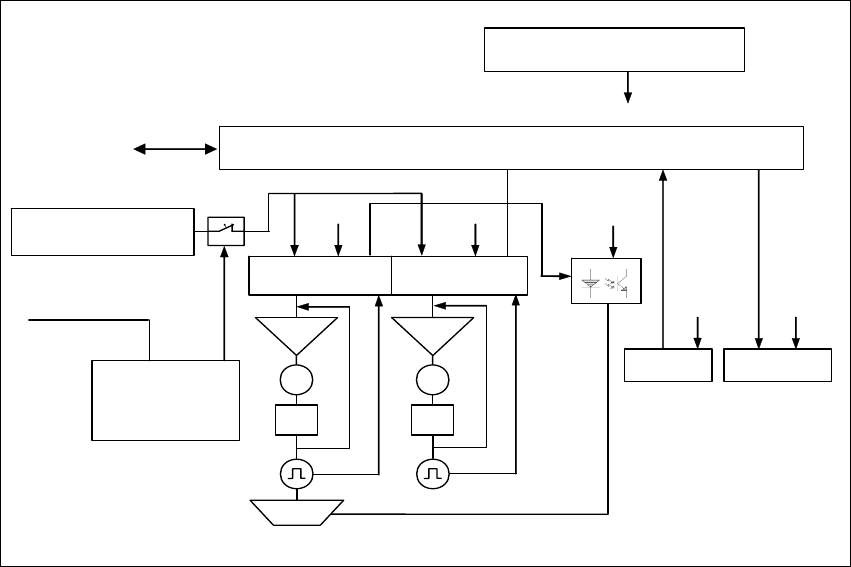
Fig. 3.1 - 1 The interfaces and power supply of the MTC 2 (shown for tower 1)
3.1.1 CAN bus
This interface is used for all commands which are sent by the machine controller of the SIPLACE
station.
Example: Reference position run and transfer of set-up data.
3.1.2 400 V power supply
The MTC 2 is supplied externally with 400 V (USA/Japan: 208/204 V).
24 V supply voltage
C167 Controller board
Servo
M
PI
Servo
M
PI
Brake
CAN bus
Sensors
RS 232
Safety
interface
400 V supply
voltage
SIPLACE
Actuators
24 V
24 V
24 V
24 V 24 V
Masterdrive
lifting axis 1
Masterdrive
feed axis 1
Safety
circuit
1
2
3
4