00193631-0602.pdf - 第62页
5 Feed axes Adjustment Instructions MTC 2 5.2 Zero offset, removal position and transfer position 12/2007 Edition 62 5.2.3 Checking and setting the zero offset Carry out the relev ant preparat ory measur es (see sectio…
Adjustment Instructions MTC 2 5 Feed axes
12/2007 Edition 5.2 Zero offset, removal position and transfer position
61
5.2 Zero offset, removal position and transfer position
NOTE
You must carry out the steps described for checking and calibrating the removal positions
for WTCs 2 - 5 on tower 1 and
for WTCs 2 -4 on tower 2.
The removal position for WTC 1 corresponds to the zero position (zero offset).
WARNING
You may only check and calibrate the positions of the feed axis with the correct zero position and
correct transfer positions of the lifting axis.
5.2.1 Tools and accessories
– Adjustment gauge, WTC
– Adjustment gauge, WTC XL
5.2.2 Preparatory measures
NOTE
The positions must be checked and calibrated with cassettes in the towers. There must be a WTC
in the bottom level of each cassette.
Set the MTC 2 up completely with empty cassettes (see the User Manual).
Set up every cassette with an empty WTC in the bottom level.
5 Feed axes Adjustment Instructions MTC 2
5.2 Zero offset, removal position and transfer position 12/2007 Edition
62
5.2.3 Checking and setting the zero offset
Carry out the relevant preparatory measures (see section 5.2.2 "Preparatory measures").
Select SITEST --> MTC --> Settings
Press the button "Teach zero point"
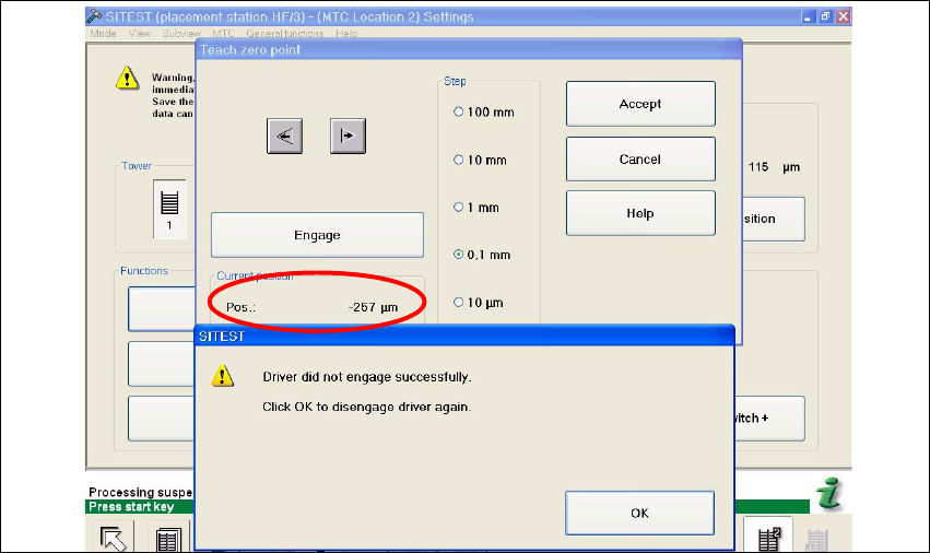
Check the position of the driver with the button "ENGAGE". In case the driver did not engaged
successfully you must determine the middle of the notch of the waffel pack tray.
The accurate adjustment is described below:
Determine the minimum position of the notch Fig. 5.2 - 1.
Fig. 5.2 - 1 Minimum position
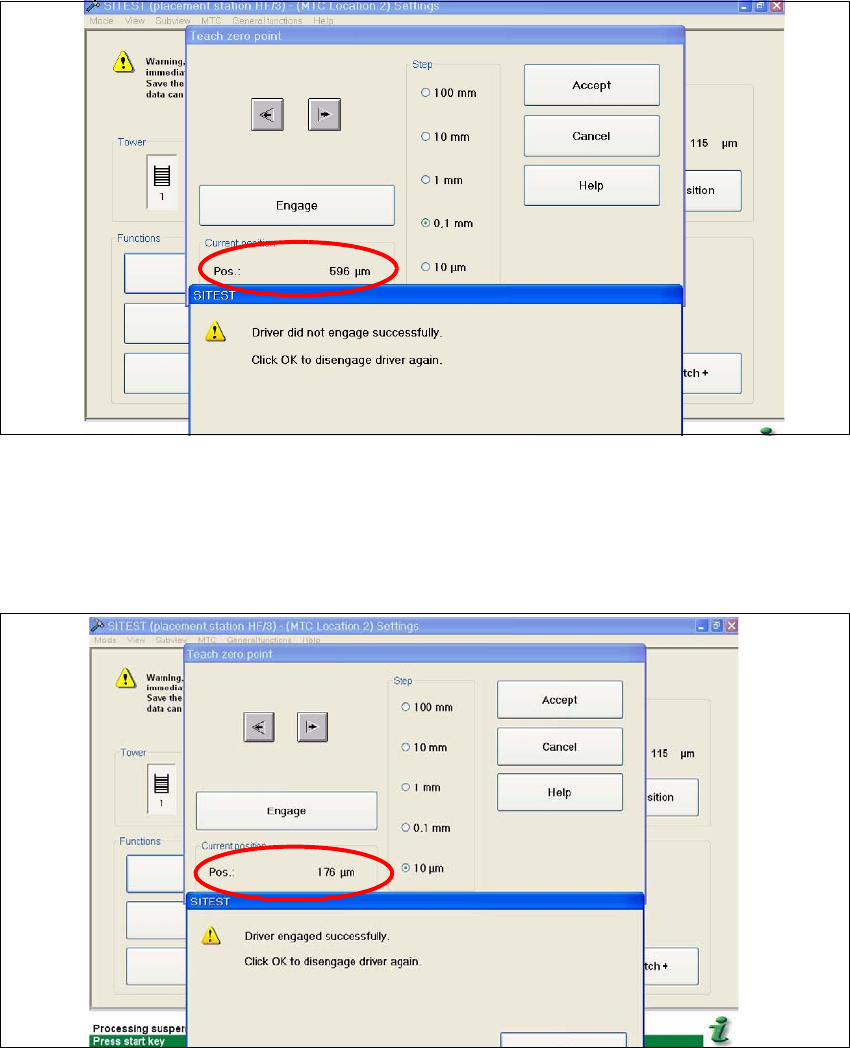
Determine the maximum position of the notch Fig. 5.2 - 2. at which the driver just engages no
more.
Adjustment Instructions MTC 2 5 Feed axes
12/2007 Edition 5.2 Zero offset, removal position and transfer position
63
Fig. 5.2 - 2 Maximum position
Now calculate the middle position at which the driver will always engage.
e.g. |-257| + 596 = 853 divided 2 = 426µm
426 + the minimum pos. or maximum pos. - 426 = approx.169µm
Fig. 5.2 - 3 Correct position for the driver
Check the driver position. The driver now should be correctly in the middle position of the notch
of the WTC.
Press the button "ACCEPT"
Check the position of the driver for the other cassettes.