00193631-0602.pdf - 第77页
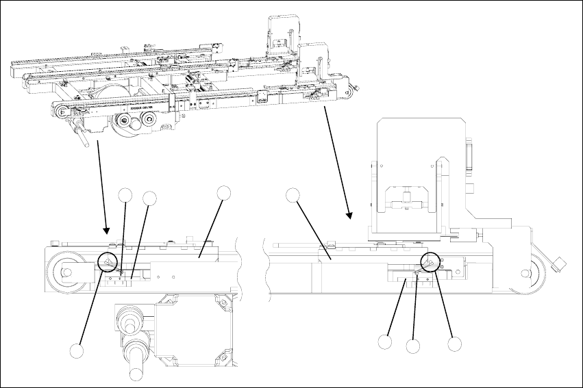
Adjustment Instr uctions MTC 2 5 Feed axes 12/2007 Edition 5.4 Limit switch 77 Fig. 5.4 - 1 Setting the maximum and minimum positi ons of the limit switches (shown her e for tower 1) Key 1. Driver at the transfer positio…

5 Feed axes Adjustment Instructions MTC 2
5.4 Limit switch 12/2007 Edition
76
5.4 Limit switch
5.4.1 Tools and accessories
– 1 set of hexagon socket wrenches
– 1 set of screw drivers
5.4.2 Preparatory measures
NOTE
Before the limit switches are set, the zero offset and the transfer position must be checked.
Check the zero offset (see section 5.2.3 "Checking and setting the zero offset").
5.4.3 Setting the limit switches
Move the feed axis into the transfer position (see section 4.2.4 "Checking the transfer positi-
ons").
Set the maximum position of the limit switch above its limit switch holder until there is a di-
stance of approximately 1 mm between the driver in the transfer position and the contact roller
of the limit switch.
Move the feed axis into the zero position (see section 5.2.3 "Checking and setting the zero
offset").
Set the minimum position of the limit switch above its limit switch holder until there is a distance
of approximately 1 mm between the driver in the zero position and the contact roller of the limit
switch (approximately 10 mm on tower 2).
Check the end positions of the feed axis (see section 5.3.2 "Checking and calibrating the end
positions").
Adjustment Instructions MTC 2 5 Feed axes
12/2007 Edition 5.4 Limit switch
77
Fig. 5.4 - 1 Setting the maximum and minimum positions of the limit switches (shown here for tower 1)
Key
1. Driver at the transfer position
2. Driver at the zero position
3. Limit switch maximum position with contact roller
4. Limit switch minimum position with contact roller
5. Limit switch holder
6. Contact area driver/limit switch at maximum position
7. Contact area driver/limit switch at minimum position
2
1
5
3
5
4
6
7
5 Feed axes Adjustment Instructions MTC 2
5.5 Light barriers 12/2007 Edition
78
5.5 Light barriers
WARNING
You may only check and calibrate the light barriers of the feed axis with the correct zero positions,
transfer positions and removal positions of the lifting and feed axes.
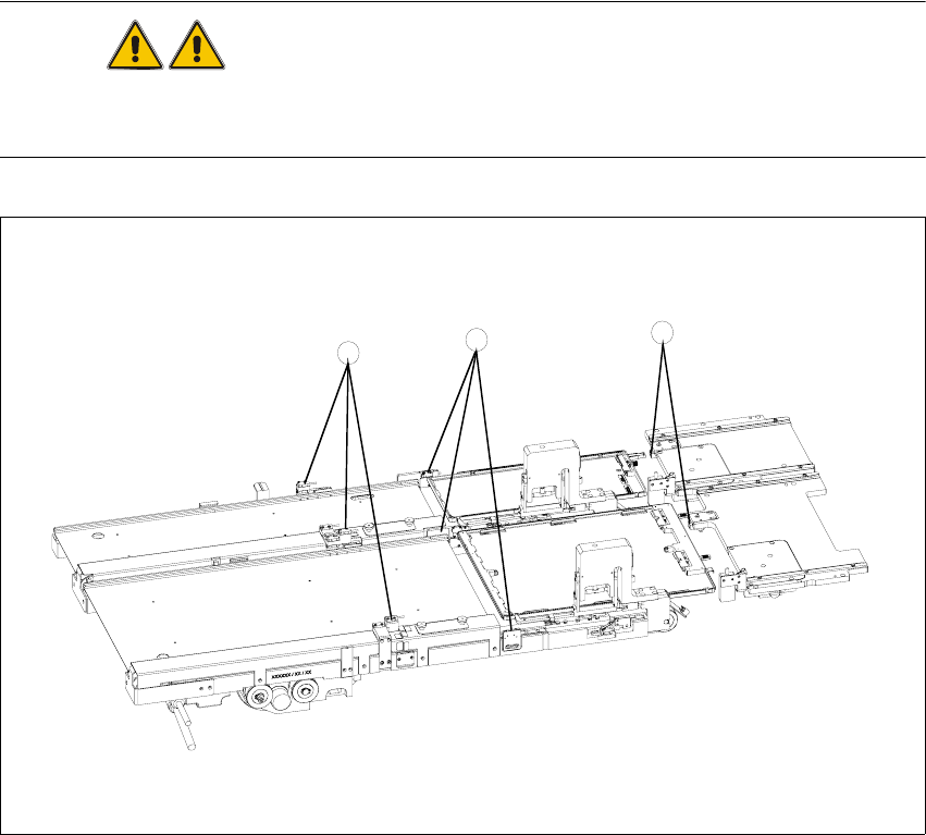
Fig. 5.5 - 1 Light barriers on the feed axes
Key
1. Handle sensor
2. WTC safety query
3. Crash light barriers
3
2
1