00193631-0602.pdf - 第86页
5 Feed axes Adjustment Instructions MTC 2 5.6 Disengaging mechanism 12/2007 Edition 86 5.6.3 Setting the disengaging mechanism Move the driver over the belt until it lies out side the disengaging mechanism. Check tha…
Adjustment Instructions MTC 2 5 Feed axes
12/2007 Edition 5.6 Disengaging mechanism
85
5.6 Disengaging mechanism
5.6.1 Tools and accessories
– 1 set of hexagon socket wrenches
5.6.2 Preparatory measures
Empty the MTC 2 completely (see the User Manual).
Move the feed axis into the zero position (see section 5.2.3 "Checking and setting the zero
offset") and engage the driver in the WTC.
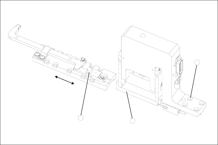
5 Feed axes Adjustment Instructions MTC 2
5.6 Disengaging mechanism 12/2007 Edition
86
5.6.3 Setting the disengaging mechanism
Move the driver over the belt until it lies outside the disengaging mechanism.
Check that the driver in its dead center position engages centrally with the disengaging aper-
ture when it is moved back.
When the guide roller is pushed through the middle of the aperture, set the position of the aper-
ture with the 4 securing screws of the disengaging mechanism.
Fig. 5.6 - 1 Setting the disengaging mechanism
Key
1. Driver guide roller in dead center position
2. Disengaging mechanism aperture
3. Disengaging mechanism securing screws
2
3
1

Adjustment Instructions MTC 2 6 Converting the power supply
12/2007 Edition 6.1 Tools and accessories
87
6 Converting the power supply
To operate the MTC 2 in the USA or in Japan, the power supply needs to be changed from 400 V,
50 Hz to 208/204 V, 50/60 Hz.
NOTE
To convert the power supply from 208/204 V to 400 V, the same procedure must be carried out in
the reverse order.
DANGER
The following activities require access to machine parts that are moved or carry dangerous
voltage. Only perform the activity that is described and do not touch any other live or moving parts.
Because of the intermediate circuit capacitors, there are still dangerous voltages in the device up
to 5 minutes after disconnection. You must therefore not work on the device or the intermediate
circuit terminals before an appropriate time has elapsed. The power and control terminals may
also still be live after the motor comes to a standstill.
There is a risk of death, severe injury and/or considerable damage to equipment if these
instructions are not followed.
6.1 Tools and accessories
– 1 set of screwdrivers
– 3 additional bridges