00193631-0602.pdf - 第29页
Adjustment Instr uctions MTC 2 4 Lifting axes 12/2007 Edition 4.1 Belt tension 29 4.1 Belt tension 4.1.1 T ools and accessories – Belt frequency mea surement device (inductive) – 2 belt tension stickers – 1 set of hexago…
4 Lifting axes Adjustment Instructions MTC 2
12/2007 Edition
28
Cassette guide rails
The cassette guide rails guide cassettes onto the tabletops during refilling.
WARNING
Incorrectly set machine data can result in a crash between the lifting and feed axes or at the limit
positions of these axes.
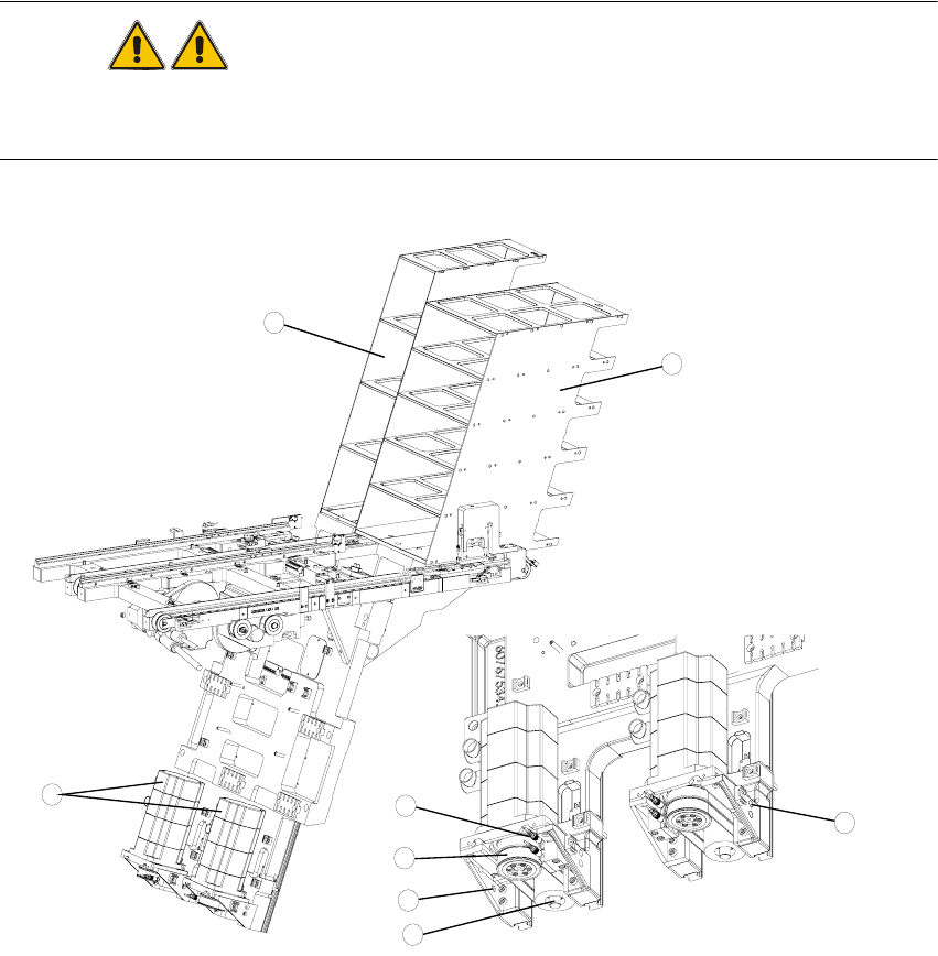
Fig. 4.0 - 1 Overview of the lifting axes
Key
1. Lifting axis tower 1
2. Lifting axis tower 2
3. Servo motors of the lifting axes
4. Dual toothed belt (shown here for tower 2)
5. Spindle (shown here for tower 2)
6. Inductive sensors (shown here for tower 2)
7. Holes for the measurement head of the belt frequency measuring device
3
2
6
4
5
1
7
7
Adjustment Instructions MTC 2 4 Lifting axes
12/2007 Edition 4.1 Belt tension
29
4.1 Belt tension
4.1.1 Tools and accessories
– Belt frequency measurement device (inductive)
– 2 belt tension stickers
– 1 set of hexagon socket wrenches
– 1 set of open-ended wrenches
4.1.2 Preparatory measures
Empty the MTC 2 completely (see the User Manual).
Move the lifting axis to its lowest position (see section 4.3.3 "Moving to the end positions").
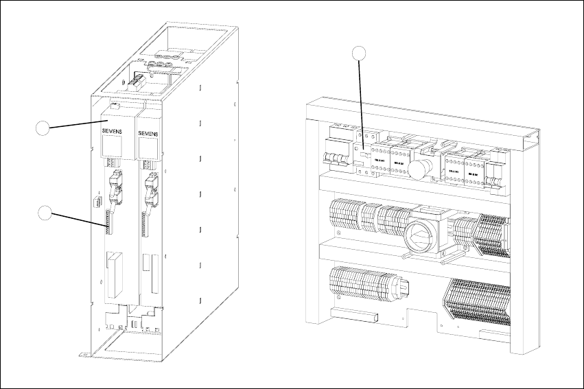
Fig. 4.1 - 1 Connections to the Masterdrives of the lifting axes
Key
1. Masterdrive, lifting axis (shown here for tower 1)
2. Connection terminal for external signals
3. Motor protection switch on the electronics board
2
1
3

4 Lifting axes Adjustment Instructions MTC 2
4.1 Belt tension 12/2007 Edition
30
DANGER
The following activities require access to machine parts that are moved or carry dangerous
voltage. Only perform the activity that is described and do not touch any other live or moving parts.
There is a risk of death, severe injury and/or considerable damage to equipment even if only one
of these instructions is not followed.
Remove the left cover in front of the electronics board and the covers on the right and the left
in front of the Masterdrives (see Fig. 3.4 - 1).
Switch the motor protection switch off (see Fig. 3.4 - 2).
To relieve the tension the toothed belts, loosen the brake on the servo motor in the following
way to rest the lifting axis on the buffer:
Check that the MTC 2 has been switched off and is isolated from the power supply.
Remove the connector for external signals from the Masterdrive for the lifting axis (see Fig.
4.1 - 1, item 2).
Move the cable from Pin 3 to Pin 1.
Attach the connector.
Connect the MTC 2 to the power supply and switch it on.
The lifting axis audibly moves a distance of a few mm up to the buffer.
Check that the lifting axis is actually at its end position.
Reconnect the cable as it was originally in the following way:
Switch off the MTC 2 and isolate it from the power supply.
Remove the connector for external signals from the Masterdrive for the lifting axis (see Fig.
4.1 - 1, item 2).
Move the cable from Pin 1 to Pin 3.
Attach the connector.
Switch the motor protection switch on.
Attach the covers.
Undock the MTC 2 from the SIPLACE station (see User Manual).
Crank up the MTC 2 in a clockwise direction until it stops.