00193631-0602.pdf - 第71页
Adjustment Instr uctions MTC 2 5 Feed axes 12/2007 Edition 5.2 Zero offset, removal position and tran sfer position 71 5.2.7 Calibrating the transfer position Carry out the relevant prep aratory measures (see section 5…
5 Feed axes Adjustment Instructions MTC 2
5.2 Zero offset, removal position and transfer position 12/2007 Edition
70
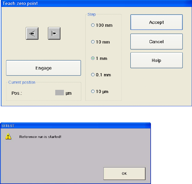
Confirm by clicking on "Accept".
Confirm your choice by clicking on "OK".
Repeat this calibration procedure for the other cassettes.
Adjustment Instructions MTC 2 5 Feed axes
12/2007 Edition 5.2 Zero offset, removal position and transfer position
71
5.2.7 Calibrating the transfer position
Carry out the relevant preparatory measures (see section 5.2.2 "Preparatory measures").
Transfer position of the Tower 1 XL WTC
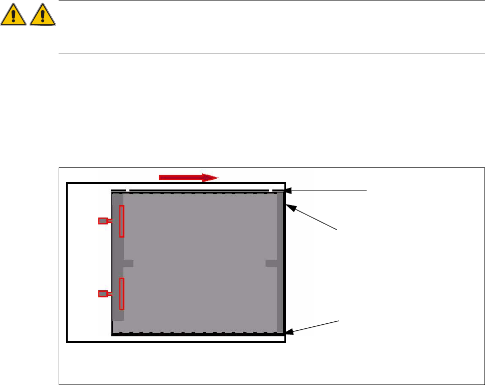
When you press the button to calibrate the Transfer position the tray moves approx. 5mm outside
of the feed axis.
Attention:
When you accept this calibration procedure with "ACCEPT" now, you get a wrong transfer position
and pick up position for the twin head.
Open the cover and move the tray back in the direction to the lifting axes
Then move the tray back in the direction to the machine and stop so that the plastic edge co-
mes into line with outer edge of the frame from the feed axis. You must do this in one step,
because that you eliminate the tolerance between the space and the driver and you don‘t need
a pick up offset for the tray.
Fig. 5.2 - 4 Transfer position XL tray
Plastic edge of the WTC
Edge of the frame from the MTC
Plastic edge of the WTC
5 Feed axes Adjustment Instructions MTC 2
5.2 Zero offset, removal position and transfer position 12/2007 Edition
72
2b. Transfer position of the Tower 2 WTC
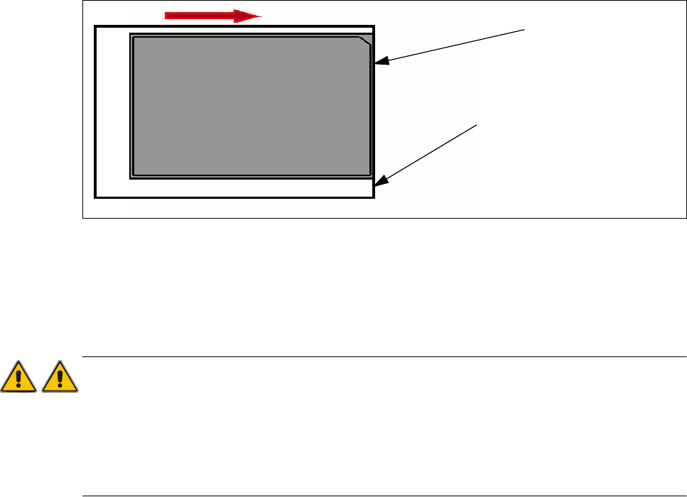
When you press the button to calibrate the Transfer position the tray moves out and stops approx.
5mm before the feed axis end.
Then move the tray in the direction to the machine and stop so that the plastic edge comes into
line with outer edge of the frame from the feed axis. You must do this in one step, because that
you eliminate the tolerance between the space and the driver and you don‘t need a pick up
offset for the tray.
Fig. 5.2 - 5 Transfer position JEDEC tray
During the production the trays move a different way to her pick up position but the Y Position of
the machinen (pick up postion) of both trays is the same.
Attention:
When you accept this calibration procedure with "ACCEPT" now, you get a wrong transfer position
and pick up position for the twin head.
The transfer position of tower 1 is situated a few millimeters further than the end of the feed axis,
of tower 2 it is situated a few millimeters before the end of the feed axis.This offset is automatically
calculated and adjusted.
Plastic edge of the WTC
Edge of the frame from the MTC