00193631-0602.pdf - 第26页
3 Construction and mode of operation Adjustment Instructions MTC 2 3.5 Block diagrams 12/2007 Edition 26
Adjustment Instructions MTC 2 3 Construction and mode of operation
12/2007 Edition 3.5 Block diagrams
25
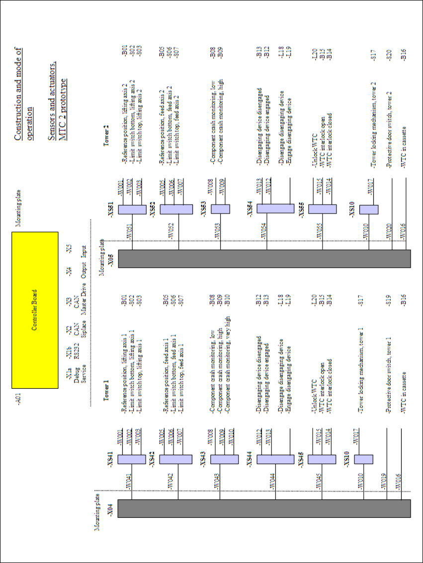
Fig. 3.5 - 3 Block diagram, sensors and actuators
3 Construction and mode of operation Adjustment Instructions MTC 2
3.5 Block diagrams 12/2007 Edition
26

Adjustment Instructions MTC 2 4 Lifting axes
12/2007 Edition
27
4 Lifting axes
NOTE
Setup activities require the SITEST program. All the steps described for one tower also apply to
the second tower.
WARNING
All screws locked with red screw locking varnish must be locked again after an adjustment has
been made.
Before carrying out work on the motors of the lifting axes, you must ensure that the lifting axis is
moved to the lowest position so that it can be rested against the buffer. Otherwise the lifting axis
may drop a significant distance when the motor brakes are put out of action.
There is a risk of injury and/or damage to machinery if these instructions are not followed.
Zero offset (zero position)
The zero offset is used to define the refill position of cassette 1. The zero offset is the difference
between the physical home position of the lifting axis and the refill position of cassette 1.
Refill positions (operator removal positions)
At the refill positions of cassettes 1 - 5 (tower 2: cassette 1 - 4), the cassettes can be removed
from the tower by the operator. The relevant cassette is located at the level of the tabletop which
is used as an aid in removal and feeding.
Transfer positions (WTC removal positions)
At the transfer positions of WTCs 1 - 5 (tower 2: WTCs 1 - 4) the lowest WTC in each cassette
can be moved onto the rails of the feed axis by the driver.
End positions (min. and max. position)
The end positions of an axis are reached when contact is made with the relevant limit switch. The
value determined here is used as a safety constraint when values are entered in the service menu
of the controller software.
Guide rails and stopper bars
The guide rails and stopper bars ensure that operation is only restored after refilling if the
cassettes and WTCs have been inserted correctly. They prevent them from inadvertently straying
out of the locked position during operation.