80S-20用户手册.pdf - 第149页
SIPLACE 80S -20/F4 User Manual 4 Placement functions Software version SR.407.xx 01/2001 US Edition 4.1 Setup display 149 4 Placement functions 4.1 Setup disp lay If the clu ster has be en specif ied with its correspo ndi…
3 Introduction and basic concepts SIPLACE 80S-20/F4 User Manual
3.3 User interface - views and menus Software version SR.407.xx 01/2001 US Edition
148
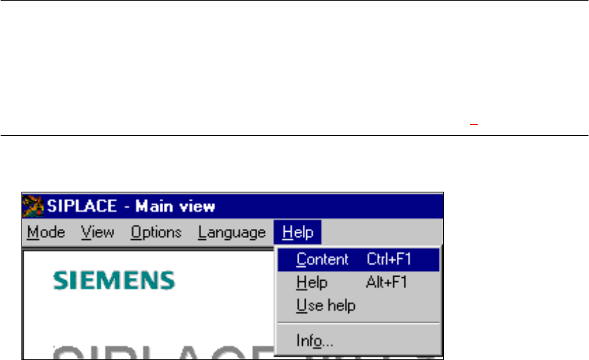
3.3.2.5 "Help" menu
This menu gives you access to all the functions required to call the help system and general infor-
mation concerning the station computer or the software. 3
Content Ctrl+F1 3
This calls on-line help. 3
Help Alt+F1 3
Help information relating to the current view is displayed. 3
Use help 3
Information on how to use Help is displayed. 3
Info ... 3
This displays information on the currently installed software version (SC , MC, WPC, GEM
version) together with general information on the station computer. 3
NOTE
You can use the key combination CTRL+F1 to call the on-line Help function from within any view
in the user interface.
You can use the key combination Alt+F1 to call up help on the current view and the key combi-
nation Shift+F1 to access help on menu items, icons and buttons.
For a detailed description of the functions in the Help menu, refer to Chapter 9. 3
Å Click the required menu item in the "Help" menu or press the corresponding key combination.
3
SIPLACE 80S-20/F4 User Manual 4 Placement functions
Software version SR.407.xx 01/2001 US Edition 4.1 Setup display
149
4 Placement functions
4.1 Setup display
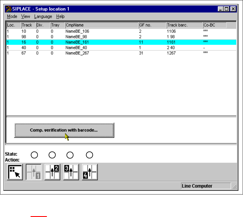
If the cluster has been specified with its corresponding setup, then the setup of each of the 4
locations can be displayed in this view.
4
Fig. 4.1 - 1 ’Setup location 1’ view
Key to Fig. 4.1 - 1
(1) Display setup for location 1
(2) Display setup for location 2
(3) Display setup for location 3
(4) Display setup for location 4
1
2
3
4

4 Placement functions SIPLACE 80S-20/F4 User Manual
4.1 Setup display Software version SR.407.xx 01/2001 US Edition
150
4.1.1 "Setup location x" view
4
Å Click on the icon in the toolbar in the Main view.
The user interface switches to the "Setup location x" view.
The setup data for the current location is presented in the display area in tabular form.
NOTE
The view is the same for each location. 4
4.1.1.1 Meaning of the entries in the setup table
– Loc.
The number of the location whose setup is to be displayed is entered in this column. (See
Chapter 3
, Fig. 3.1 - 2 for the position of the locations)
– Track
The number of the track on which the corresponding feeder or waffle pack tray is located is
entered here.
– Div.
The number of the feeder division from which the component in the corresponding feeder is to
be picked up, or the number of the waffle pack tray compartment from which the component is
picked up is entered in this column.
– Tray
The number of the level in the waffle pack tray from which the component is picked up is en-
tered in this column.
(Only valid for automatic placement machines with wafflepack changers).
– CmpName
The name of the corresponding component is entered in this column.
– GF no.
The number of the package form for the corresponding component is entered here.
– Track barc.
The track barcode assigned to the corresponding track is entered in this column.