80S-20用户手册.pdf - 第441页
SIPLACE 80S -20/F4 User Manual 10 Component handling Software version SR.407.xx 01/2001 US Edition 10.3 Setting up the feeder modules 441 10.3 Settin g up the feed er modul es 10.3.1 Prepari ng the component tabl e and m…

10 Component handling SIPLACE 80S-20/F4 User Manual
10.2 Technical data for the feeder modules Software version SR.407.xx 01/2001 US Edition
440
10.2.13.1 Functional description
The component disposal module has essentially the same structure as a feeder. The only differ-
ence is that it has an empty tape, rather than a component tape. Faulty components can be placed
in the pockets of this empty tape without damaging them. This means that these components can
subsequently be manually checked, repaired and thus reused. The advantage of the disposal con-
veyor is that the operator can remove the separated components without having to interrupt the
placement process. Once all the pockets on the conveyor belt are full, a message appears on the
monitor, prompting the operator to remove the components. 10
10.2.13.2 System requirements
The following system requirements must be fulfilled in order to use the component disposal mod-
ule: 10
Line software version 501.01 or later
Station software version 405.01 or later
Feeder table software version 3.09 or later
PLEASE NOTE:
The component disposal module must be configured on the line computer and activated on the
station computer. 10
10.2.13.3 Conditions for disposal of components using the component disposal module
A component is placed on the disposal conveyor if the following conditions are fulfilled: 10
10
– The component type to be disposed of must be included in the set-up on the line computer.
– The component must be identified for return.
– Components to be disposed of from a carrier tray must already have been wetted with flux in
the dip fluxer. If this is not the case, they will be returned to the tray.
10
10

SIPLACE 80S-20/F4 User Manual 10 Component handling
Software version SR.407.xx 01/2001 US Edition 10.3 Setting up the feeder modules
441
10.3 Setting up the feeder modules
10.3.1 Preparing the component table and module for set-up
Å Select the setting range for the feeder module to be used
(see Vibrator configuration).
Å Move the placement head to the waiting position and press the emergency stop button.
Å Open the protective covers.
Å Clean the contact surface for the feeder modules and the contact surface for the feeder mod-
ules on the component table.
Å Place the feeder module on the previously selected track on the component table (see Vibrator
configuration).
10.3.2 Inserting the module
Å Insert the module so that the back of the module is held by the centering ball and the front is
fixed in place by the corresponding centering pin on the component table. Make sure that the
module is placed on the component table in the correct position for its width.
Å Check that the module is firmly seated on the component table.
Å Connect the module plug to the socket beneath the location.
PLEASE NOTE 10
When you connect the module, make sure that you use the right socket for the location since
the module receives the control pulse via this socket. The feeder module may not work cor-
rectly if it is not connected to the right socket. 10
Å Close the protective covers and switch the control on again.
Å Carry out a refill check if necessary.
Å Continue placement.
10 Component handling SIPLACE 80S-20/F4 User Manual
10.3 Setting up the feeder modules Software version SR.407.xx 01/2001 US Edition
442
10
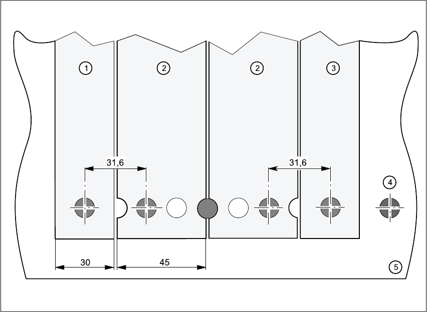
Fig. 10.3 - 1 Inserting 30 or 45 mm wide feeder modules on the component table
(1) Feeder module, 30 mm wide
(2) Feeder module, 45 mm wide
(3) Feeder module, 30 mm wide