80S-20用户手册.pdf - 第60页
1 Introduction SIPLACE 80S-20 /F4 User Manual 1.13 Overview o f the modules - placement heads Software version SR.407.xx 01/2001 US Edition 60 1.13. 5 Desc ription of the Pick&Place he ad The Pick & Pl ace head w…
SIPLACE 80S-20/F4 User Manual 1 Introduction
Software version SR.407.xx 01/2001 US Edition 1.13 Overview of the modules - placement heads
59
1.13.4 Structure of the Pick&Place head
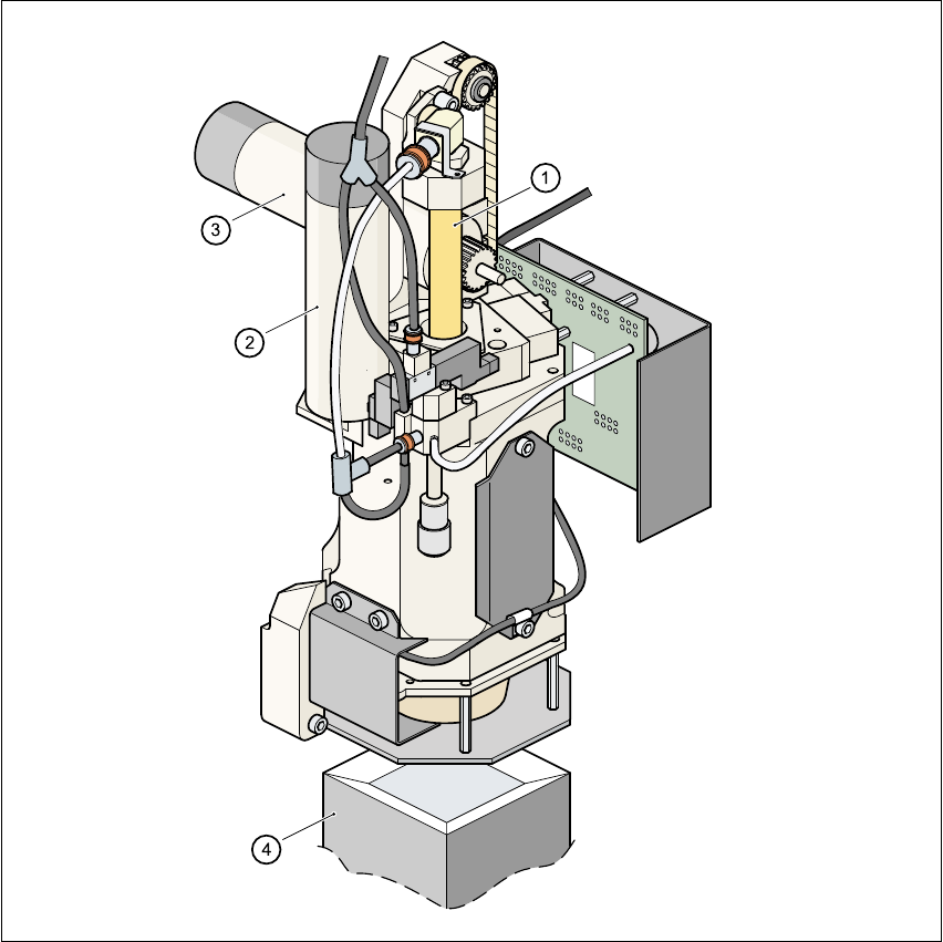
1
Fig. 1.13 - 2 Structure of the Pick&Place head.
(1) Sleeve
(2) DR axis driving mechanism
(3) Z axis driving mechanism
(4) Fine pitch vision module

1 Introduction SIPLACE 80S-20/F4 User Manual
1.13 Overview of the modules - placement heads Software version SR.407.xx 01/2001 US Edition
60
1.13.5 Description of the Pick&Place head
The Pick&Place head works according to the pick&place principle, which means that a compo-
nent is picked up by the nozzle with the aid of a vacuum. After optical centering with the fine pitch
or flip chip vision module, the component is turned to the correct placement angle, and inserted
into the PCB with high precision. The Pick&Place is particularly striking because of its high angu-
lar accuracy. 1
1.13.6 Technical data - Pick&Place head
Component range up to 55mm x 55mm
Max. height
Component height ≤ 13.5mm - PCB thickness
- PCB sagging
Option:
Component height ≤ 20mm - PCB thickness
- PCB sagging
Min. lead pitch 0.4mm (standard), 0.25mm (option)
Max. dimensions
up to 32mm x 32mm with single measurement
up to 55mm x 55mm with quadruple measurement
Max. weight 25 g
Programmable placement
force
1 - 10 N
Nozzle types
4xx, 5 standard nozzles including flip chip nozzle with nozzle
changer
Component centering
Fine pitch component vision module (standard)
Flip chip vision module (option)
Benchmark placement rate 1,800 components/hour
D axis resolution 0.005°
Angular accuracy ± 0.052° / 3 σ, ± 0.07° / 4 σ, ± 0.105° / 6 σ
Placement accuracy ± 37.5 µm / 3 σ, ± 50 µm / 4 σ, ± 75 µm / 6 σ

SIPLACE 80S-20/F4 User Manual 1 Introduction
Software version SR.407.xx 01/2001 US Edition 1.14 Overview of the modules - vision systems
61
1.14 Overview of the modules - vision systems
Every machine has 1
– a PCB vision module on the Collect&Place head,
– a fine pitch component vision module on the machine base, and
– a PCB vision module on the underside of the X-axis gantry
1
The vision evaluation unit is located on the machine’s control unit. The component vision module
is used to 1
– determine the precise position of the component at the nozzle, and
– the geometry of the package form.
1
The PCB vision module uses fiducials on the PCB to determine 1
– the position of the PCB,
– its rotational angle,
– and the PCB distortion.
Damaged PCBs or subpanels are marked with ink spots. The PCB vision module scans the ink
spots, and signals that these circuits should not be placed. 1
The PCB vision module also uses fiducials on the feeders to determine the precise component
pick-up position. This is particularly important for tiny components. 1
1.14.1 Technical data of the component vision module on the 12-segment
Collect&Place head
Max. component dimensions 0.5mm x 1.0mm to 18.7mm x 18.7mm
Component range
0402 to PLCC44
including BGA, µBGA, flip chip, TSOP, QFP
PLCC, SO to SO32, DRAM
Minimum lead pitch ≥ 0.5 mm
Field of view 24mm x 24mm
Method of illumination Front lighting (3 levels programmable as required)