80S-20用户手册.pdf - 第66页
1 Introduction SIPLACE 80S-20 /F4 User Manual 1.15 Overview o f the modules - PCB conveyor Software version S R.407.xx 01/2001 US E dition 66

SIPLACE 80S-20/F4 User Manual 1 Introduction
Software version SR.407.xx 01/2001 US Edition 1.15 Overview of the modules - PCB conveyor
65
1
1
PCB transport height
830mm ± 15mm (standard)
900mm ± 15mm (option)
930mm ± 15mm (option)
950mm ± 15mm (SMEMA: optional)
Fixed conveyor edge Right (standard), left (optional)
Type of interface Siemens (standard), (SMEMA: optional)
Component-free handling edge 3mm
PCB changeover time 2.5 s
Components on each conveyor Synchronous: same or different, asynchronous: same
PCB width on each conveyor Synchronous: different, asynchronous: same
Ink spot recognition Synchronous: not possible, asynchronous: possible
Automatic width adjustment Synchronous: not possible, asynchronous: possible
1 Introduction SIPLACE 80S-20/F4 User Manual
1.15 Overview of the modules - PCB conveyor Software version SR.407.xx 01/2001 US Edition
66
SIPLACE 80S-20/F4 User Manual 2 Operational Safety
Software version SR.407.xx 01/2001 US Edition 2.1 Safety instructions
67
2 Operational Safety
2.1 Safety instructions
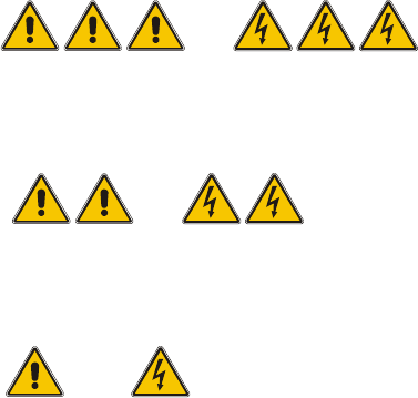
2.1.1 Conventions for the use of hazard symbols
This User Manual contains notes that must be observed to guarantee your personal safety and to
avoid damage to equipment. These notes are highlighted by warning triangles and are indicated
as follows according to the level of risk: 2
2
DANGER or 2
as used in this User Manual means that death, severe injury or considerable damage to equip-
ment may occur if the danger instructions are not followed. 2
2
WARNING or 2
as used in this User Manual means that death, severe injury or considerable damage to equip-
ment may occur if the warning instructions are not followed. 2
2
CAUTION or 2
as used in this User Manual means that slight injury or damage to equipment may occur if the cau-
tion instructions are not followed. 2
2
PLEASE NOTE 2
as used in this User Manual provides information on the product or indicates a part of the User
Manual that requires particular attention. 2
2.1.2 Qualified personnel
Qualified or adequately trained personnel means that these people are familiar with the setting up,
operation and maintenance of automatic placement systems and add-on devices and are suitably
qualified, e.g. 2
– have been trained, instructed or authorized to switch on and off, isolate, earth and identify elec-
trical circuits and system components in accordance with normal safety standards.