80S-20用户手册.pdf - 第505页
SIPLACE 80S-20/F4 User Manual 11 Station extensions /Hardware Software version SR.407.xx 01/2001 US Edition 11.9 Flux dispenser unit 505 1 1 .9.3 Functional description The cen trifugal tube ( 3) is use d as a reser voir…

11 Station extensions /Hardware SIPLACE 80S-20/F4 User Manual
11.9 Flux dispenser unit Software version SR.407.xx 01/2001 US Edition
504
11.9 Flux dispenser unit
11.9.1 Overview
Reliable processing of flip-chip components requires a flux to be applied before the component is
placed. This ensures that the subsequent soldering process will be successful. 11
Once the Pick&Place head has picked up the flip-chip component, and a position measurement
has been carried out, the flux is dispensed at the placement position on the PCB. The volume of
flux to be dispensed can be entered for specific package forms. 11
The Pick&Place head inserts the flip-chip component as soon as the flux has been dispensed.
The Pick&Place head hold the flip-chip component in position on the PCB for a programmable,
package form-specific time. This causes the component to dry onto the flux, thus preventing it
from “floating away”. 11
Once all the flip-chip components have been placed, the PCB conveyor is activated after a pro-
grammable waiting time in order to remove the PCB. 11
11.9.2 Technical data
11
Dispensing volume 2 µl - 100 µl
Smallest dosing increment 1 µl
Syringe volume 1 ml
Tank volume 100 ml
Volume to be dispensed at the mounting location Depends on the flip-chip size, and the wetting prop-
erties of both flux and substrate material.
Flip-chip holding time after placement 0 to 5 sec
Holding time increment 0.01 sec
Minimum waiting time before PCB is transported 0 to 40 sec
Waiting time increment 1 sec
Dispensing cycle time 1.5 sec, including positioning
Rinse cycle 1 to 10 x syringe content
Filling level 1 Warning
Filling level 2 Empty, i.e. machine stopped
Positioning accuracy of the dispensing needle ± 0.05 mm
SIPLACE 80S-20/F4 User Manual 11 Station extensions /Hardware
Software version SR.407.xx 01/2001 US Edition 11.9 Flux dispenser unit
505
11.9.3 Functional description
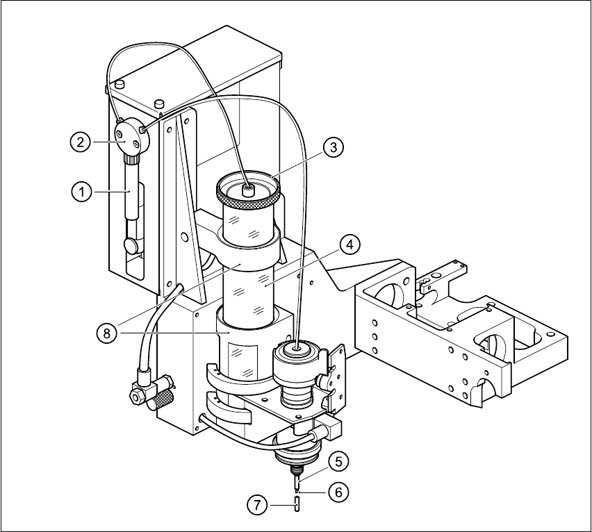
The centrifugal tube (3) is used as a reservoir, and is filled with flux. A pump sucks the flux via the
valve (2) up into the syringe (1). The syringe (1) then dispenses the set volume of flux, via the
valve and the tip of the dispensing needle (6), onto the placement position. 11
11
Fig. 11.9 - 1 Fluxing overview
(1) Syringe (2) Valve
(3) Cover of reservoir (4) Reservoir (centrifugal tube)
(5) Centering nozzle (6) Tip of dispensing needle
(7) Press-fit cap (8) Retainer
11 Station extensions /Hardware SIPLACE 80S-20/F4 User Manual
11.9 Flux dispenser unit Software version SR.407.xx 01/2001 US Edition
506
CAUTION
If the flux dispenser is likely to be out of service for any time (more than 1 hour), the press-fit cap
must be pulled over the centering nozzle. This will prevent the flux from crystallizing, and thus
sealing the centering nozzle. 11
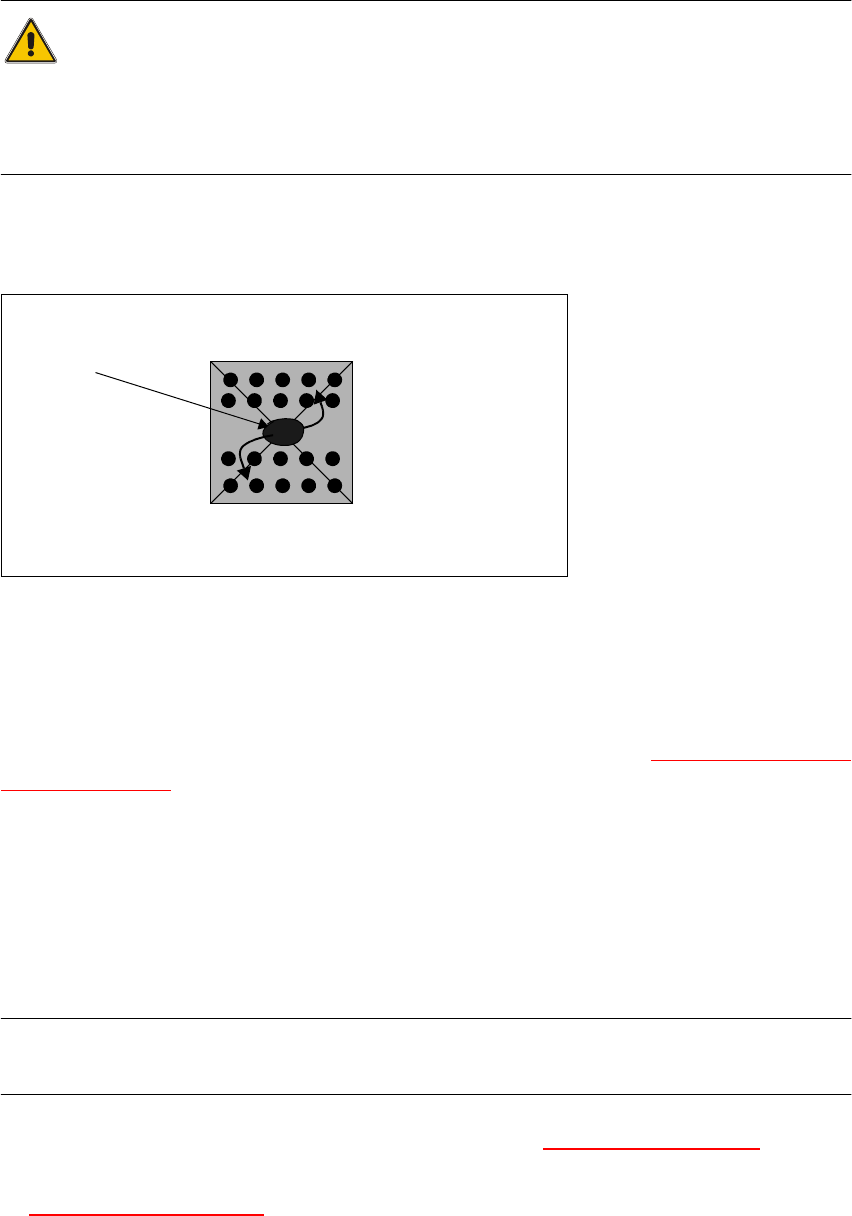
The flip-chip component is inserted at the placement position, and held in position for a pre-set
time to allow the flux to dry. 11
Fig. 11.9 - 2 Principle of a component with flux
(1) The flux charge runs to the leads
11
The PCB then remains in the machine for a variable period to ensure that the flux has dried fully. 11
The procedure for entering the required parameters is described in Section 11.9.7.1 Package form
list and parameters. 11
11.9.4 Refilling the flux
A warning is output at the station computer when the flux has to be refilled. It is possible to con-
tinue placement for a short period, but the reservoir should not be allowed to run dry in order to
avoid unwanted periods of stoppage. 11
PLEASE NOTE
The reservoir must be refilled off the machine to prevent flux being dropped into the machine. 11
Å Move the fluxer head into the refill position. See Section 11.9.7.4 Single functions
Å Pull the reservoir up and out of its retainer, and turn the lid to remove it from the tank. See Fig.
11.9 - 1 "Fluxing overview"
.
111