80S-20用户手册.pdf - 第59页
SIPLACE 80S -20/F4 User Manual 1 Introduction Software version SR.407.xx 01/2001 US Edition 1.13 Overview of the modules - placement heads 59 1.13.4 Structure of the P ick & Place head 1 Fig. 1.13 - 2 St ructure of t…

1 Introduction SIPLACE 80S-20/F4 User Manual
1.13 Overview of the modules - placement heads Software version SR.407.xx 01/2001 US Edition
58
– The component vision camera creates an image of the current component.
– The precise position of the component is also determined.
– The package form of the current component is compared against the programmed package
form in order to identify it. Any components that cannot be identified are rejected.
– The turning station turns the component to the required placement angle.
1.13.2 Description of the 12-segment Collect&Place head
– The 12-segment Collect&Place head works using the "Collect & Place" principle, i.e. the com-
ponents are held by the nozzles with the aid of a vacuum and, after one complete pick-up cycle,
are placed gently and accurately on the PCB with the aid of blast air. The vacuum in the noz-
zles is also checked several times to determine whether the components were picked up and
set down correctly.
– The "adaptive" sensor stop mode of the Z-axis compensates for any irregularity of the
PCB-surface when the components are set down.
– Defective components are rejected, and are reworked during a repair cycle.
1.13.3 Technical data of the 12-segment Collect&Place head
Component range 0402 to 18.7mm x 18.7mm including BGA, µBGA,
flip chip, TSOP, QFP, PLCC, SO to SO32, DRAM
Max. height 6 mm
Min. lead pitch 0.5 mm
Min. dimensions 0.5 mm x 1.0 mm
Max. dimensions 18.7 mm x 18.7 mm
Max. weight 2 g
Max. travel of z axis 16 mm
Programmable placement force 2.4 to 5.0 N
Nozzle types 7xx
Angular accuracy ± 0.525° / 3 σ, ± 0.70° / 4 σ, ± 1.05° / 6 σ
Placement accuracy ± 67.5 µm / 3 σ, ± 90 µm / 4 σ, ± 135 µm / 6 σ
SIPLACE 80S-20/F4 User Manual 1 Introduction
Software version SR.407.xx 01/2001 US Edition 1.13 Overview of the modules - placement heads
59
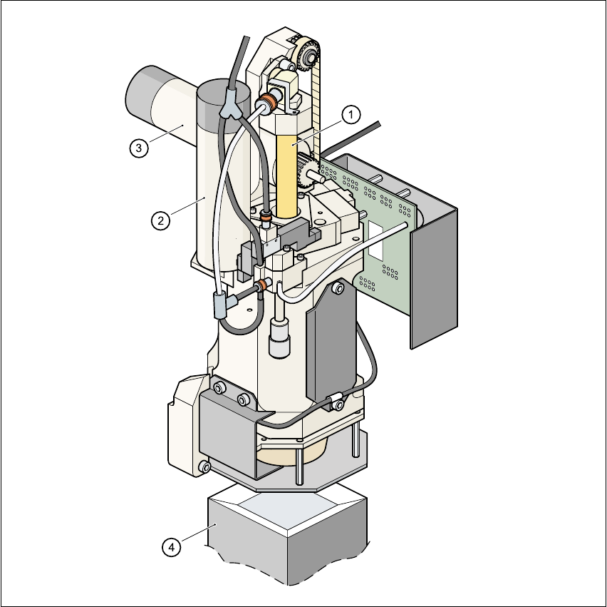
1.13.4 Structure of the Pick&Place head
1
Fig. 1.13 - 2 Structure of the Pick&Place head.
(1) Sleeve
(2) DR axis driving mechanism
(3) Z axis driving mechanism
(4) Fine pitch vision module

1 Introduction SIPLACE 80S-20/F4 User Manual
1.13 Overview of the modules - placement heads Software version SR.407.xx 01/2001 US Edition
60
1.13.5 Description of the Pick&Place head
The Pick&Place head works according to the pick&place principle, which means that a compo-
nent is picked up by the nozzle with the aid of a vacuum. After optical centering with the fine pitch
or flip chip vision module, the component is turned to the correct placement angle, and inserted
into the PCB with high precision. The Pick&Place is particularly striking because of its high angu-
lar accuracy. 1
1.13.6 Technical data - Pick&Place head
Component range up to 55mm x 55mm
Max. height
Component height ≤ 13.5mm - PCB thickness
- PCB sagging
Option:
Component height ≤ 20mm - PCB thickness
- PCB sagging
Min. lead pitch 0.4mm (standard), 0.25mm (option)
Max. dimensions
up to 32mm x 32mm with single measurement
up to 55mm x 55mm with quadruple measurement
Max. weight 25 g
Programmable placement
force
1 - 10 N
Nozzle types
4xx, 5 standard nozzles including flip chip nozzle with nozzle
changer
Component centering
Fine pitch component vision module (standard)
Flip chip vision module (option)
Benchmark placement rate 1,800 components/hour
D axis resolution 0.005°
Angular accuracy ± 0.052° / 3 σ, ± 0.07° / 4 σ, ± 0.105° / 6 σ
Placement accuracy ± 37.5 µm / 3 σ, ± 50 µm / 4 σ, ± 75 µm / 6 σ