80S-20用户手册.pdf - 第498页
11 Station extensions /Hardware SIPLACE 80S-20 /F4 User Manual 11.8 Coplanarity laser module (80F4) Sof tware version SR.407.xx 01/2001 US Edition 498 The coplan arity l aser mod ule is com bined with opt ical co mponent…
SIPLACE 80S-20/F4 User Manual 11 Station extensions /Hardware
Software version SR.407.xx 01/2001 US Edition 11.8 Coplanarity laser module (80F4)
497
11.8 Coplanarity laser module (80F
4
)
11.8.1 Functional description
The coplanarity laser module is used to measure vertical bending of the leads. The lead length is
measured without contact using the laser triangulation principle. 11
The placement head picks up the component to be checked, centers it optically using the IC cam-
era, and moves all four sides one after another over the fixed laser beam of the coplanarity laser
module. In this way, every lead is scanned from below by the laser beam. The laser light scattered
by the underside of the lead is recorded by a sensor, and is then used to calculate the exact po-
sition of the lead with respect to the PCB. The position values thus calculated are compared
against the limit value specified by the user. If they exceed this value, the component is disposed
of or reworked. 11
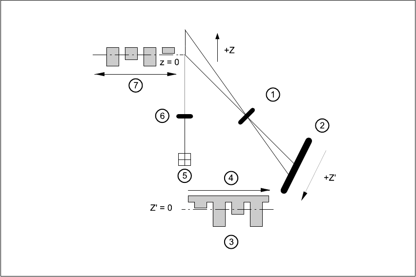
Fig. 11.8 - 1 Principle of laser triangulation
(1) Receiver lens (2) Detector
(3) Measuring signal (4) Time t
(5) Laser (6) Transmitter lens
(7) Travel direction 11

11 Station extensions /Hardware SIPLACE 80S-20/F4 User Manual
11.8 Coplanarity laser module (80F4) Software version SR.407.xx 01/2001 US Edition
498
The coplanarity laser module is combined with optical component centering, and is used in a
vision module. Components with bent or missing leads are detected and disposed of, if necessary.11
11.8.2 Technical data
Component range: Can be used for gull wing components, pitch 0.3
The component size and lead pitch are limited by the
component position recognition system,
i.e. max. size 43.0 mm x 43.0mm x 11.0 mm.
Measuring principle:
Contact-free measurement by laser triangulation
Algorithm functions: JEDEC standard calculation of the placement plane, all
deviations are determined in relation to this plane. If the
component is angled with respect to the vacuum nozzle, as can
happen if an adapter is used, then it will have no influence over
the choice between ‘good’ and ‘bad’.
Output: < 5 mW
Measuring range: ± 2.5 mm
Laser focus: elliptical, 50µm x 95µm
Thermal stability: ± 1µm/K
Wavelength: 670 nm
Resolution: 0.25µm
Scanning frequency: 10 kHz
Weight: 500 g
Operating temperature: 0°C ... 40
Humidity: 5 - 95% non-condensing
Ambient pressure: Atmospheric pressure
Vibration: to IEC 68-2-6
Mechanical shock: to IEC 68-2-27
EMC: to EN 50081-2 emitted interference
to EN 50082-2 immunity to interference
Degree of protection: IP 64
Mech. dimensions: 118 mm x 30 mm x 125.5 mm
Permissible ambient light: 30,000 lx
Safety: The coplanarity laser module conforms to laser class 1
when installed in the machine. The module will not work when
off the machine unless further devices are installed or
the protective functions are modified. If the protective functions
on the device are bypassed, the machine automatically conforms
to laser class 3B – Risk of injury to eyes and skin
-
and thus requires protective measures to VBG 93.
SIPLACE 80S-20/F4 User Manual 11 Station extensions /Hardware
Software version SR.407.xx 01/2001 US Edition 11.8 Coplanarity laser module (80F4)
499
11.8.3 Safety instructions
DANGER
NEVER modify or bypass safety devices on the coplanarity laser module. 11
11
With no protective measures, the coplanarity
laser module conforms to laser class 3B.
This means there is a risk of injury to eyes
and skin.
For this reason, you should NEVER
bypass the safety
devices. 11
11
11
11
11
11
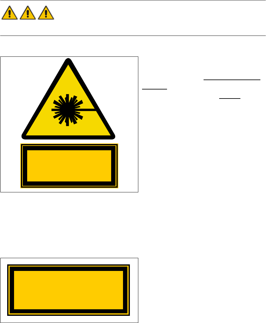
Fig. 11.8 - 2 Identification for laser class 3B
11
The following safety devices must be installed on the machine if the laser module is to be operated
in laser class 1 without risk to the eyes and skin. 11
11
The interlock line is connected in series with
the switches for the protective hood. This pro-
tective function is maintained even if the key
switch is turned to bypass the protection. This
means that the laser module can only be
used if the machine is closed. 11
Fig. 11.8 - 3 Identification of laser class 1
Invisible laser radiation
Do not expose the beam
Class 3 B Laser Product
1mW max., 670 nm; n. IEC 825-1(1993)
Class 1 Laser Product