Oxford-100-Manual.pdf - 第100页
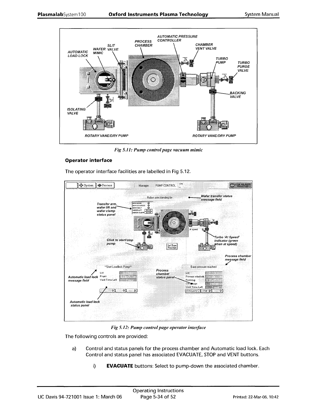
PlasmalabSystem 100 Oxford Instruments Plasma Technology AUTOMADCPRESSURE CONTROLLER System Manual TURBO PURGE VALVE ROTARY VANE/DRY PUMP ROTARY VANE/DRY PUMP Fig 5.11: Pump control page vacuum mimic Operator interface T…
System
Manual
Oxford
Instruments
Plasma
Technology
PlasmalabSystem100
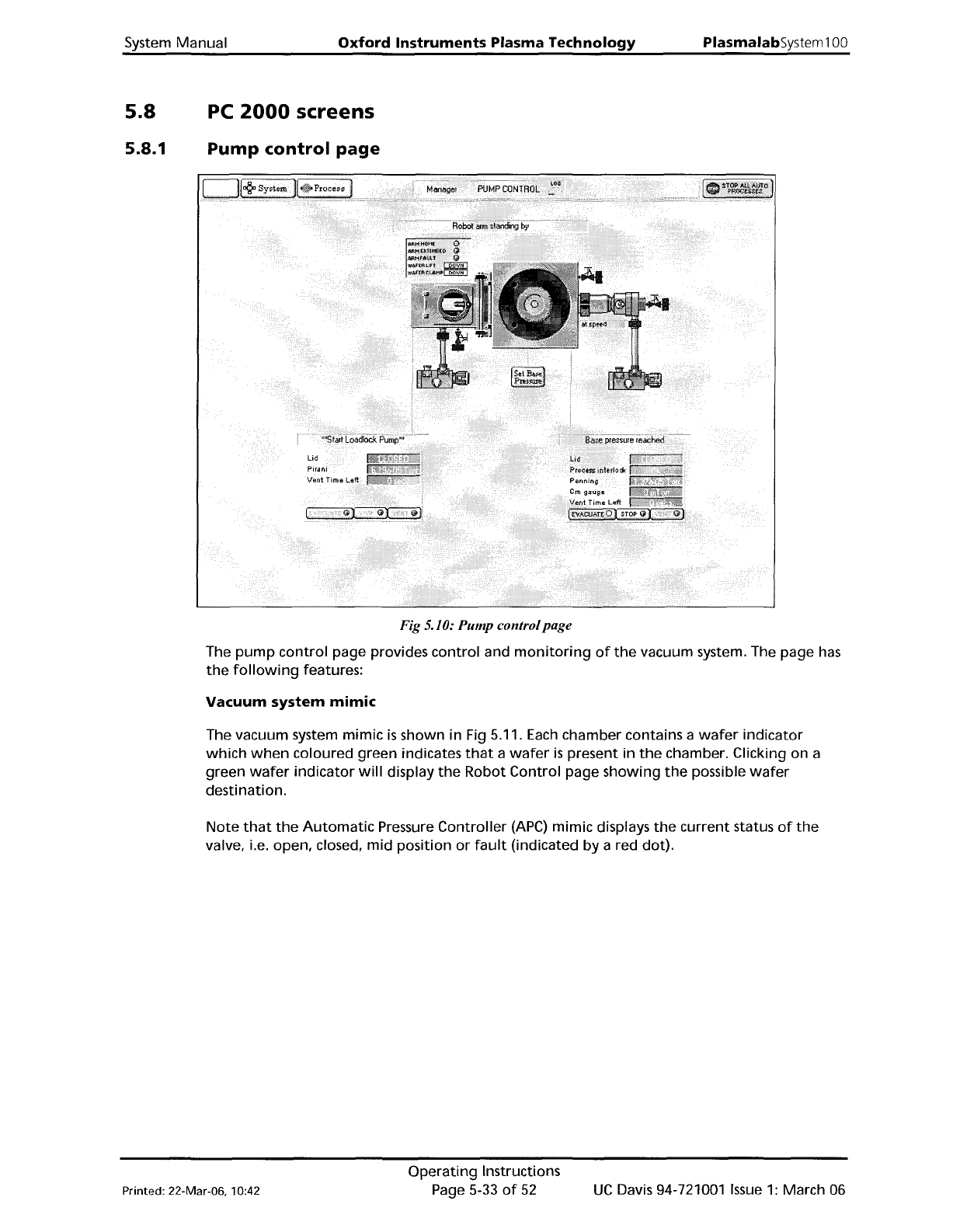
5.8
5.8.1
PC
2000
screens
Pump
control
page
Fig 5.10: Pump controlpage
The
pump
control
page provides
control
and
monitoring
of
the
vacuum system. The page
has
the
following
features:
Vacuum
system
mimic
The vacuum system
mimic
is
shown in Fig 5.11.
Each
chamber contains a
wafer
indicator
which
when
coloured green indicates
that
a
wafer
is
present in
the
chamber. Clicking on a
green
wafer
indicator
will
display
the
Robot
Control
page
showing
the
possible
wafer
destination.
Note
that
the
Automatic
Pressure
Controller
(APC)
mimic displays
the
current
status
of
the
valve, i.e. open, closed,
mid
position
or
fault
(indicated
by
a red dot).
Printed: 22-Mar-06, 10:42
Operating
Instructions
Page 5-33
of
52
UC
Davis 94-721001
Issue
1:
March 06
PlasmalabSystem100
Oxford
Instruments
Plasma
Technology
AUTOMADCPRESSURE
CONTROLLER
System Manual
TURBO
PURGE
VALVE
ROTARYVANE/DRY PUMP ROTARYVANE/DRY PUMP
Fig 5.11: Pump controlpage vacuum mimic
Operator
interface
The
operator
interface
facilities are labelled in Fig 5.12.
Fig 5.12: Pump controlpage operator interface
The
following
controls are provided:
a)
Control and status panels
for
the
process chamber and
Automatic
load lock.
Each
Control
and status panel has associated EVACUATE,
STOP
and VENT buttons.
i)
EVACUATE buttons: Select
to
pump-down
the
associated chamber.
UC
Davis 94-721001
Issue
1:
March 06
Operating
Instructions
Page 5-34
of
52
Printed: 22-Mar-06, 10:42
System
Manual
Oxford
Instruments
Plasma
Technology
PlasmalabSystem100
ii) STOP buttons: Select
to
stop
either
pumping
down
or
venting
the
associated chamber.
Note
that
the
STOP
button
must be selected
before
venting
to
ensure
the
correct sequencing
of
the
valves.
iii)
VENT
buttons:
Select
to
vent
the
associated chamber.
b) Mimics
of
all valves
showing
open/closed status (coloured green
when
open, red
when
closed).
c)
Rotary/dry
pump
controls. Clicking
on
a
rotary
vane/dry
pump
mimic
button
will
switch
the
associated
pump
on
or
off
(a
running
rotary
pump
is
indicated by
animation).
d) Transfer arm,
Wafer
lift
and
Wafer
clamp status panel. Displays indicators
for
ARM
HOME, ARM
EXTENDED
and ARM FAULT
(illuminated
when
active). Also displays
WAFER
LIFT
and
WAFER
CLAMP status (up,
down,
moving
or
fault).
See
the
following
table.
MessaQe
MeaninQ
UP
The
UP
microswitch
is
detected
as
active.
DOWN
The DOWN microswitch
is
detected
as
active.
MOVING Both microswitches are detected
as
inactive.
FAULT Both microswitches are detected
as
active.
e)
The run status
of
the
turbo
pump
is
indicated
by
an associated message panel
containing
an indicator.
While
the
turbo
pump
is
running
up
to
speed,
the
message
'accelerating'
is
displayed and
the
indicator
is
flashing
yellow.
While
the
turbo
pump
is
at
its
operating
speed,
the
message
'at
speed'
is
displayed and
the
indicator
is
green.
f)
A
SET
BASE
PRESSURE
button.
Select
to
set
the
Process
Chamber
Base
Pressure.
g)
Context
related message panels
for
the
process chamber,
Automatic
load lock and
wafer
transfer
progress.
h) 'Ready
for
transfer'
indicators (
....
~)
- displayed
when
the
associated chamber
or
load
lock
is
evacuated and ready
for
wafer
transfers.
Printed: 22-Mar-06. 10:42
Operating
Instructions
Page 5-35
of
52
UC
Davis 94-721001
Issue
1:
March 06