Oxford-100-Manual.pdf - 第232页
OIPT Systems Oxford Instruments Plasma Technology System Manual 6. Process gases I====+-.... REGULATOR 0.5 BAR TO 5 BAR ....... (7 TO 75 PSIG) LOCATED ....... ADJACENT TO THE SYSTEM ' ............ , "- '--…
System
Manual
5.
Nitrogen
Oxford
Instruments
Plasma
Technology
OIPT Systems
Nitrogen
is
required
to
vent
and
purge
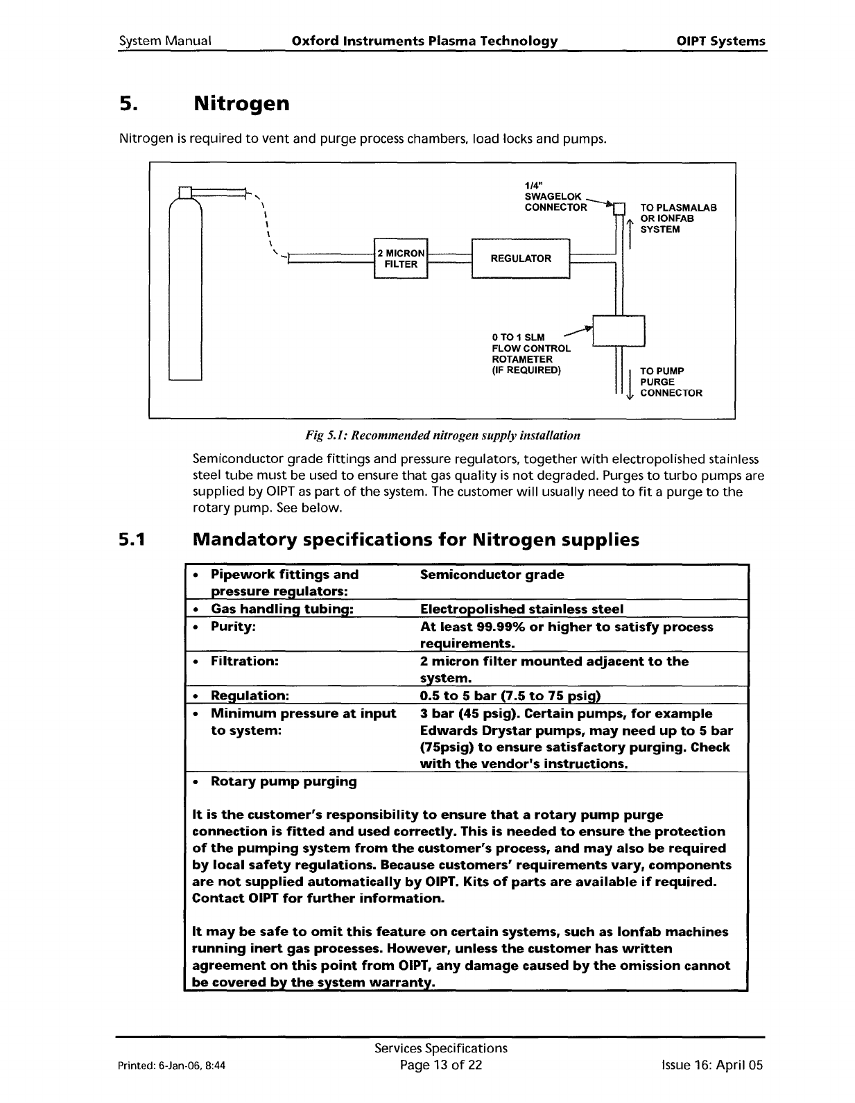
process chambers, load locks and pumps.
il====::::r-
"
\
I
\
I
\
"
1/4"
SWAGELOK
CONNECTOR
REGULATOR
OT01SLM
FLOW CONTROL
ROTAMETER
(IF REQUIRED)
TO
PLASMALAB
t
ORIONFAB
I SYSTEM
1
TOPUMP
PURGE
CONNECTOR
Fig 5.1: Recommendednitrogen supply installation
Semiconductor
grade
fittings
and pressure regulators,
together
with
electropolished stainless
steel
tube
must
be used
to
ensure
that
gas
quality
is
not
degraded. Purges
to
turbo
pumps are
supplied
by
DIPT
as
part
of
the
system. The customer
will
usually need
to
fit
a
purge
to
the
rotary
pump.
See
below.
5.1
Mandatory
specifications
for
Nitrogen
supplies
•
Pipework
fittings
and
Semiconductor
grade
pressure reQulators:
•
Gas
handling
tubing:
Electropolished stainless steel
•
Purity:
At
least
99.99%
or
higher
to
satisfy process
reQuirements.
•
Filtration:
2
micron
filter
mounted
adjacent
to
the
system.
•
ReQulation:
0.5
to
5
bar
(7.5
to
75
psig)
•
Minimum
pressure
at
input
3
bar
(45
psig).
Certain
pumps,
for
example
to
system:
Edwards
Drystar
pumps,
may
need
up
to
5
bar
(75psig)
to
ensure
satisfactory
purging.
Check
with
the
vendor's
instructions.
•
Rotary
pump
purging
It
is
the
customer's
responsibility
to
ensure
that
a
rotary
pump
purge
connection
is
fitted
and
used correctly. This is
needed
to
ensure
the
protection
of
the
pumping
system
from
the
customer's
process,
and
may
also
be
required
by
local
safety
regulations.
Because customers'
requirements
vary,
components
are
not
supplied
automatically
by
OIPT. Kits
of
parts
are
available
if
required.
Contact
OIPT
for
further
information.
It
may
be
safe
to
omit
this
feature
on
certain
systems, such
as
lonfab
machines
running
inert
gas processes.
However,
unless
the
customer
has
written
agreement
on
this
point
from
OIPT,
any
damage
caused
by
the
omission
cannot
be
covered
by
the
system
warranty.
Printed: 6-Jan-06. 8:44
Services Specifications
Page
13
of
22
Issue
16:
April
05
OIPT
Systems
Oxford
Instruments
Plasma
Technology
System
Manual
6.
Process
gases
I====+-....
REGULATOR 0.5
BAR
TO 5
BAR
.......
(7
TO 75 PSIG) LOCATED
.......
ADJACENT TO THE SYSTEM
'
............
,
"-
'---~
/
SUPPLY
TO
GAS POD
OR INTERNAL
GAS LINE
MINIMUM PRESSURE
3
BAR
(45 PSIG)
-
NOTES:
ALL
TUBING TO BE
ELECTROPOLISHED
STAINLESS STEEL
ALL
FITTINGS,
REGULATOR AND
FILTER TO BE
SEMICONDUCTOR
GRADE
6.1
6.1.1
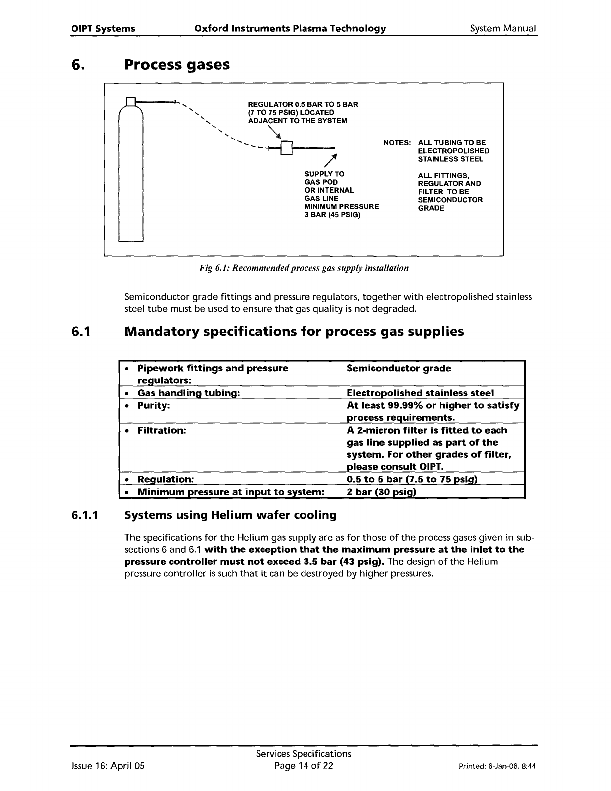
Fig 6.1: Recommendedprocessgas supply installation
Semiconductor
grade
fittings
and pressure regulators,
together
with
electropolished stainless
steel
tube
must be used
to
ensure
that
gas
quality
is
not
degraded.
Mandatory
specifications
for
process
gas
supplies
•
Pipework
fittings
and
pressure
Semiconductor
grade
re~ulators:
•
Gas
handlin~
tubin~:
Electropolished
stainless
steel
•
Purity:
At
least
99.99%
or
higher
to
satisfy
process
requirements.
•
Filtration:
A
2-micron
filter
is
fitted
to
each
gas
line
supplied
as
part
of
the
system.
For
other
grades
of
filter,
please
consult
OIPT.
•
Regulation:
0.5
to
5
bar
(7.5
to
75
psig)
•
Minimum
pressure
at
input
to
system:
2
bar
(30
psi~)
Systems
using
Helium
wafer
cooling
The specifications
for
the
Helium gas supply are
as
for
those
of
the
process gases given in sub-
sections 6 and
6.1
with
the
exception
that
the
maximum
pressure
at
the
inlet
to
the
pressure
controller
must
not
exceed
3.5
bar
(43
psig).
The design
of
the
Helium
pressure
controller
is
such
that
it
can
be
destroyed
by
higher
pressures.
Issue
16:
April
05
Services Specifications
Page 14
of
22
Printed: 6-Jan-06, 8:44
System
Manual
Oxford
Instruments
Plasma
Technology
OIPT Systems
6.1.2
Installation
of
low
vapour
pressure gases
(e.g.
SiCI
4
•
BCI
3
•
C
4
F
s
)
The
low
vapour
pressure can lead
to
condensation in
the
gas supply lines,
particularly
at
cold
points
or
when
the
gas
passes
into
a cooler region. This condensation can result
in
a
build
up
of
liquid
in
the
gas pipe, usually
at
the
low
points
or
u-bends in
the
gas line,
often
leading
to
instability
of
gas
flow,
especially
if
liquid
condenses
or
flows
into
the
MFC.
The
low
vapour
pressure can also result in very
low
gas pressure
if
the
gas cylinder
is
very
cold, e.g.
if
it
is
kept
outdoors
in
the
winter.
Therefore,
it
is
important
to
adhere
to
the
following
guidelines:
(A)
It
is
necessary
to
keep
the
gas cylinder indoors (in an extracted gas cabinet)
to
avoid
loss
of
line
pressure
when
the
outside
temperature
is
cold.
However,
do
NOT
heat
the
gas cylinder
with
a heated
jacket
as
this can cause
condensation problems
when
the
gas
passes
into
the
cooler gas lines. Room
temperature
is
warm
enough
to
provide
sufficient
vapour
pressure.
(B)
It
is
important
to
maintain
a positive
temperature
gradient
from
the
cylinder
to
the
MFC,
or
at
least keep
them
at
the
same
temperature.
The simplest
method
is
to
position
the
gas cabinet close
to
the
gas pod,
minimising
the
chances
of
temperature
differences, reducing
the
length
of
the
gas pipe, and hence
minimising
the
chances
of
condensation.
If
this
is
not
possible,
then
it
is
necessary
to
heat
the
gas lines by
the
use
of
heater
tape.
The
MFC
will
also need
to
be heated.
OIPT
offers
a heated
MFC
kit
for
these
gases.
Alternatively,
heater
tape
can be
wrapped
around
the
MFC.
However, in this
case,
it
may
also
be
necessary
to
detach
the
MFC
from
the
backing
plate
to
avoid
heat
loss
through
the
plate, and
to
cover
the
MFC
in insulation material
to
avoid
cooling
from
air
flow
within
the
gas
pod
(from
the
gas
pod
exhaust).
It
will
then
be necessary
to
set
the
MFC
temperature
hotter
than
the
gas line
temperature,
which
in
turn
is
hotter
than
the
gas cylinder
temperature.
A typical set-
up
might
be
MFC
40
·C
or
above, gas line 30-40 ·C, and gas cylinder
at
room
temperature.
(C)
If
condensation problems are suspected,
it
will
be necessary
to
pump
out
the
gas
lines completely, and optimise
the
heater
tape
arrangement
and
temperature
setpoints
before
refilling
the
gas line.
(0) For
SiCI
4
it
is
important
to
use a dedicated
SiCI
4
MFC
as
this
is
designed specifically
for
low-pressure condensable
SiCI
4
operation.
Printed: 6-Jan-06, 8:44
Services Specifications
Page
15
of
22
Issue
16:
April
05