Oxford-100-Manual.pdf - 第75页
System Manual Vacuum pumps Oxford Instruments Plasma Technology PlasmalabSystem 100 An auxiliary circuit on the pump contactor detects pump failure due to overload or short circuit, and the process gases are immediately …
PlasmalabSystem1
00
Oxford
Instruments
Plasma Technology
System
Manual
5.3.7 System response
to
loss
of
services
This sub-section
briefly
describes
the
system's response
to
the
loss
of
services.
Electrical
Process and pumps stop.
Air
operated gas and vacuum valves shut.
Where
the
chamber
APC
function
and
main
chamber vacuum valve are combined in
one
unit,
it
is
automatically
closed
on
loss
of
electrical power. Load lock
wafer
transfer valve(s) retain
their
current
state,
or
finish
their
current
transition. A Hine arm
robot
will
finish its
current
movement.
Other
wafer
transfer
devices stop
moving
immediately.
Information
on
the
current
process and
wafer
position
is
lost.
Loss
of
one
of
three
phases:
rotary
vacuum
pump
stops.
If
the
phase
powering
the
process
controller
remains live
then
the
process aborts, all valves
shut
but
the
system
controller
retains
information
on
the
current
state
of
the
machine.
If
the
process
controller
phase
is
lost,
then
current
information
is
lost.
Compressed
air
All
air
operated
gas
inlet
and vacuum valves shut. (Exceptions: air-operated valves
with
electrical solenoids
unaffected;
normally
open gas
interlock
valves open).
Gas
flows
stop and
the
chamber
is
not
pumped.
Process
power(s) are
turned
off
as
soon
as
a
flow
or
pressure
exceeds a tolerance band -
normally
within
5 seconds. Load lock
wafer
transfer
valve(s)
go
to
an
undefined
state. Rotational
movement
of
the
air
operated
4-way load lock stops.
Cooling
water
Certain components are
protected
by
a
water
flow
switch.
If
the
flow
is
low,
a
warning
message
is
displayed
on
the
PC,
and
the
associated device
is
turned
off.
Leybold
dry
pumps have
their
own
internal
over-temperature
switches.
Loss
of
flow
for
these
pumps
will
eventually
cause a
temperature
trip
causing a process
abort
(process chamber
pump)
and
the
relevant
pump
to
be switched
off.
Devices such
as
turbo
pumps have
their
own
internal
protection
against overheating and are
not
protected
by external
flow
switches.
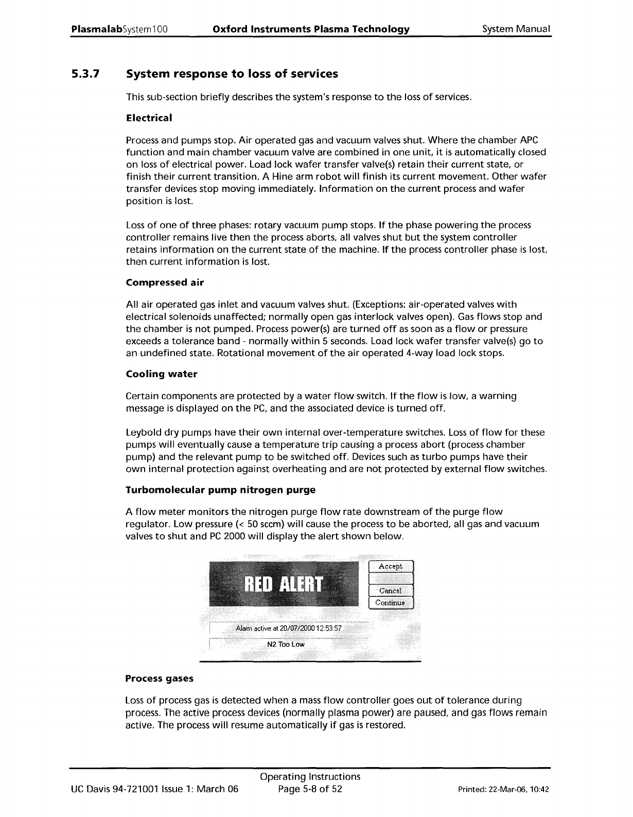
Turbomolecular
pump
nitrogen
purge
A
flow
meter
monitors
the
nitrogen
purge
flow
rate
downstream
of
the
purge
flow
regulator.
Low
pressure « 50
sccm)
will
cause
the
process
to
be aborted, all gas and vacuum
valves
to
shut and
PC
2000
will
display
the
alert
shown
below.
Process gases
Loss
of
process gas
is
detected
when
a
mass
flow
controller
goes
out
of
tolerance
during
process. The active process devices
(normally
plasma
power)
are paused, and gas
flows
remain
active. The process
will
resume
automatically
if
gas
is
restored.
UC
Davis 94-721001
Issue
1:
March 06
Operating
Instructions
Page
5-8
of
52
Printed: 22-Mar-06, 10:42
System
Manual
Vacuum
pumps
Oxford
Instruments
Plasma
Technology
PlasmalabSystem100
An
auxiliary circuit
on
the
pump
contactor
detects
pump
failure
due
to
overload
or
short
circuit, and
the
process gases are
immediately
halted.
If
a
rotary
vane
or
dry
vacuum
pump
stops
pumping
for
other
reasons
during
a process, e.g.
if
it
fails
or
its
power
is
disconnected, and
the
vacuum
interlock
switch's contacts remain closed,
process gas
will
continue
to
flow
into
the
process chamber.
Gas
flow
will
stop
when
the
chamber pressure exceeds
the
vacuum switch
trip
level
of
600
mbar
absolute. The
front-end
software
will
show
the
interlock
status
as
'fault'.
WARNING
DISCONNECTING THE POWER TO AUXILIARY EQUIPMENT, ESPECIALLY
VACUUM
PUMPS, WHILE RUNNING A PROCESS
CAN
CAUSE A HAZARD IN
THE
PROCESS
CHAMBER.
ENSURE THAT THE SYSTEM IS SHUT
DOWN
USING THE PROCEDURE GIVEN
IN
SUB-
SECTION
5.3.5
BEFORE DISCONNECTING
ANY
POWER CABLES FROM
THE
POWER
BOX, OR SWITCHING
OFF
ANY
ELECTRICAL SUPPLIES TO AUXILIARY EQUIPMENT.
WARNING
IF
THE EQUIPMENT HALTS DURING PROCESS BECAUSE THE
VACUUM
SWITCH HAS
OPENED, THERE
MAY
BE
A SERIOUS GAS HAZARD
IN
THE CHAMBER
AND
PUMPING
LINES.
ASSESS THE RISKS
BEFORE
TRYING TO PUMP OR VENT THE CHAMBER.
PERSONAL PROTECTIVE EQUIPMENT
MAY
BE
NECESSARY.
Printed: 22-Mar-06, 10:42
Operating
Instructions
Page 5-9
of
52
UC
Davis 94-721001
Issue
1:
March 06
PlasmalabSystem100
Oxford
Instruments
Plasma Technology
System
Manual
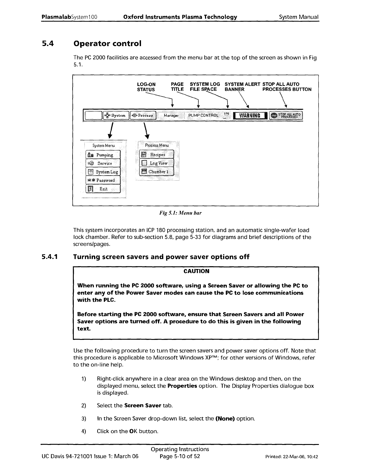
5.4
Operator
control
The
PC
2000 facilities are accessed
from
the
menu bar
at
the
top
of
the
screen
as
shown
in
Fig
5.1.
LOG-ON
PAGE
SYSTEM
LOG
SYSTEM ALERT
STOP
ALL AUTO
STA~~
S~ANN\
PROC\SBUTTON
5ystemMenu
h Pumping
~
Service
Fig 5.1:
Menu
bar
This system incorporates an
ICP
180 processing station, and an
automatic
single-wafer load
lock chamber. Refer
to
sub-section 5.8, page 5-33
for
diagrams and
brief
descriptions
of
the
screens/pages.
5.4.1
Turning screen savers
and
power
saver
options
off
CAUTION
When
running
the
PC
2000
software,
using a Screen
Saver
or
allowing
the
PC
to
enter
any
of
the
Power
Saver
modes
can cause
the
PC
to
lose
communications
with
the
PLC.
Before
starting
the
PC
2000
software,
ensure
that
Screen Savers
and
all
Power
Saver
options
are
turned
off.
A
procedure
to
do
this
is
given
in
the
following
text.
Use
the
following
procedure
to
turn
the
screen savers and
power
saver
options
off.
Note
that
this procedure
is
applicable
to
Microsoft
Windows
XpTM;
for
other
versions
of
Windows,
refer
to
the
on-line
help.
1)
Right-click
anywhere
in a clear area on
the
Windows
desktop and
then,
on
the
displayed menu, select
the
Properties
option.
The Display Properties
dialogue
box
is
displayed.
2)
Select
the
Screen
Saver
tab.
3)
In
the
Screen Saver
drop-down
list, select
the
(None)
option.
4)
Click on
the
OK
button.
UC
Davis 94-721001
Issue
1:
March 06
Operating
Instructions
Page 5-10
of
52
Printed: 22-Mar-06, 10:42