Oxford-100-Manual.pdf - 第36页
System Manual Oxford Instruments Plasma Technology Plasma lab System 100 SP91CZ f t-ril r----- 1 REGUL4 TOR G:',\,R'REGi560 V;.t..~'·~R~N :ti",t.."'i:)-tnur SP'J1i?41!1 Hi' (;GdUdd…
System
Manual
Oxford
Instruments
Plasma Technology
Plasma
lab
System
100
MINiMUM
1
".;.
~U'L"".'iJl'
iC"'''JM.
,
C----::~
. .•...
__
•
,.-
_..
. l
--_...•
---
"tiAH:Rif";
W.A.TERGur
r----------
ice
RF
GS;NER:;.
1GB
'kATE:;
~rJ
SP91[2!~
rl1
'#An:RiN
'NAiER -
SP'J1i?4171
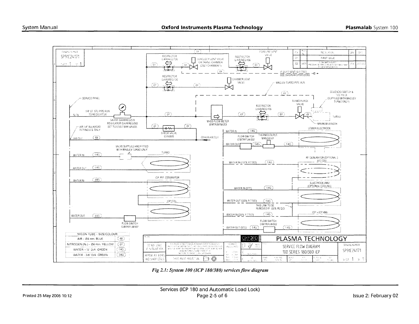
Fig 2.1: System 100 (ICP 180/380) services
flow
diagram
Printed 25
May
200510:12
Services
(lCP
180 and
Automatic
Load Lock)
Page 2-5
of
6
Issue
2:
February 02
System
Manual
Oxford
Instruments
Plasma
Technology
Plasma
lab
System 100
SP91CZ
f
t-ril
r-----
1
REGUL4
TOR
G:',\,R'REGi560
V;.t..~'·~R~N
:ti",t.."'i:)-tnur
SP'J1i?41!1
Hi'
(;GdUdd'iOI'i{jNAi.
:c---==3
--'
'
----,
.
.--
j
---
._-
-----
ViATfR
DIA
GREH'~
Fl.0Wt';'/fiI()i
N!THOG2N
;N;)
{}G
';;'<;'A':ER
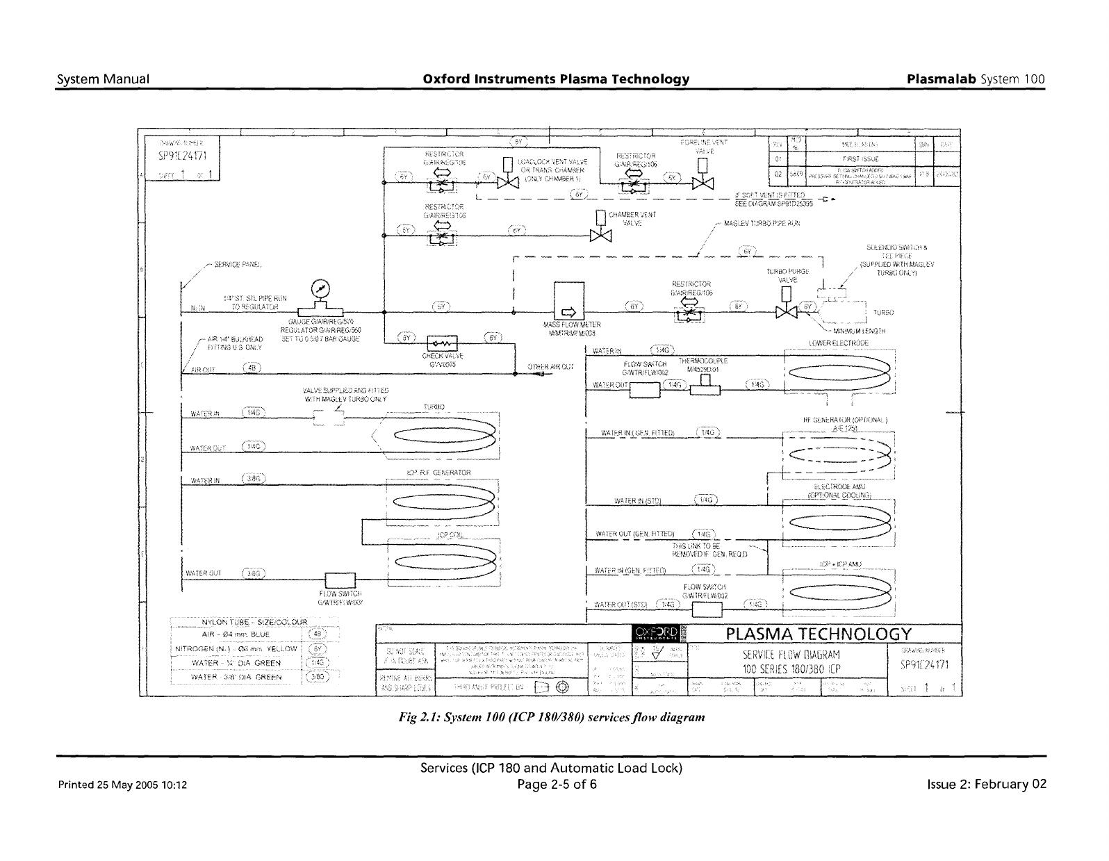
Fig 2.1: System 100 (ICP 180/380) servicesflow diagram
Printed
25 May
200510:12
Services
(lCP
180 and
Automatic
Load Lock)
Page 2-5
of
6
Issue
2: February 02
System
Manual
Oxford
Instruments
Plasma
Technology
Plasma
lab
System
100
3.
Description
3.
Description
3-1
3.1
Introduction
3-2
3.2
PC
2000
Hardware
and
software
with
licence 3-2
3.2.1
Hardware
3-2
3.2.2
PC
2000
software
and single-user Iicence
3-2
3.3
94-100-0-RIE RIE
base
unit
3-2
3.3.1 Frame
3-3
3.3.2 Power
box
assembly
3-3
3.3.3 System
controller
3-3
3.3.4 Interlocks
3-5
3.3.5 Services 3-6
3.4
94-100-3-41C
ICP
180
chamber
kit
with
gate
valve
3-7
3.4.1 94-100-3-00/21P
Process
chamber electrical
heating
kit.. 3-8
3.4.2 94-100-3-00/05 200mm
Pumpdown
pipe
heater
kit
3-8
3.5
94-100-5-12A
Cryo
1
heated
-150/400C
helium-assisted
lower
electrode
..............•••.....••..3-9
3.6
94-100-6-500/200
500W
RF
generator
1OIPT
AMU
kit
3-12
3.7
94-100-6-56ICP
180
Inductively
Coupled
Plasma Source
3-12
3.8 Vacuum
system
3-12
3.9
Gas
handling
system
3-14
3.9.1 94-81-9-51/8
Gas
pod
(PLC
version) 3-14
3.9.2 94-81-9-11 Standard
non-toxic
gas line 3-16
3.9.3 94-81-9-21 Standard toxic gas line 3-17
3.9.4 94-81-9-00/4
Gas
line
interlock
kit
3-17
3.10
94-100-10-05C
Single
wafer
automatic
load
lock
3-18
3.10.1
Wafer
transfer
mechanism
operating
principle 3-19
3.10.2 Functional Description 3-20
3.10.3
Wafer
support
(end
effector)
3-22
Fig 3.1: Typical
control
system 3-4
Fig 3.2: 94-100-3-41C process chamber
3-7
Fig 3.3: 94-100-5-12A Cryo /
heated
-150/
400C He
lower
electrode
3-11
Fig 3.4:
UC
Davis 94-721001 vacuum system 3-13
Fig 3.5: 94-81-9-51
Gas
pod
3-15
Fig 3.6: 94-81-9-11 Standard
non-toxic
gas lines 3-16
Fig 3.7: 94-81-9-21 Standard toxic gas
line
3-17
Fig 3.8: Single
wafer
automatic
load lock 3-18
Fig 3.9: Simplified
wafer
transport
mechanism
operation
3-19
Fig 3.10:
Automatic
load lock, side
view
3-20
Fig 3.11:
Automatic
load lock
wafer
transport
mechanism
3-21
Table 3.1: Consequences
of
open circuit interlocks 3-6
Printed: 22-Mar-06. 7:29
Description
Page
3-1
of
22
UC
Davis 94-721001
Issue
1:
March 06