Oxford-100-Manual.pdf - 第264页
Plasma lab ICP 180 Oxford Instruments Plasma Technology WARNING Equipment Manual BEFORE PROCEEDING WITH ANY MAINTENANCE WORK, READ SECTION 1· HEALTH AND SAFETY. 7.3.2 Automatch gives reflected power of 2% to 5% 1) Ensure…
Equipment
Manual
Oxford Instruments Plasma Technology
WARNING
Plasma
lab
ICP
180
BEFORE
PROCEEDING WITH
ANY
MAINTENANCE WORK, READ SECTION 1 • HEALTH
AND
SAFETY.
5)
Refit
the
automatch
covers.
7.3 High
reflected
power
(system
under
vacuum)
1)
Evacuate
the
process chamber. Set
up
a
flow
of
gas
to
give a pressure in
the
range 1
Pa
to
3
Pa
(7
mTorr
to
22 mTorr).
2)
Set
the
ICP
180
RF
forward
power
to
100W. Check
the
reflected
power.
Depending on
the
reflected
power
reading, proceed
as
follows:
a)
If
the
reflected
RF
power
is
<
2%
of
the
forward
RF
power,
the
automatch
is
tuned
correctly and ready
for
processing.
b)
If
the
reflected
RF
power
is
>
5%
of
the
forward
RF
power,
carry
out
the
procedure in
sub-section 7.3.1.
c)
If
the
reflected
RF
power
is
greater
than
2%
and
less
than
5%
of
the
forward
RF
power, carry
out
the
procedure in sub-section 7.3.2.
7.3.1
NOTE:
Automatch
gives
reflected
power>
5%
WARNING
THE
FOLLOWING
PROCEDURE
INVOLVES WORKING
CLOSE
TO
EXPOSED LIVE
RF
CONDUCTORS
AND
MUST ONLY
BE
CARRIED OUT
BY
SKILLED PERSONNEL WHO
ARE
FULLY
TRAINED
AND
AWARE
OF
THE
POTENTIAL HAZARDS.
The
following
text
refers
to
systems
fitted
with
an
Automatch
Unit
manual
adjustment
panel.
For systems
having
software
control
of
the
Automatch
Unit,
refer
to
Section 5
(Operating
Instructions)
of
your
system
manual
and
the
Automatch
Unit's
Equipment
Manual.
1)
2)
3)
4)
5)
6)
7)
Turn
off
the
RF
supply.
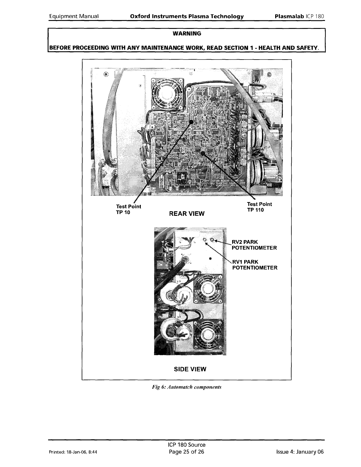
Open
the
automatch
cover
to
reveal
the
automatch
PCB
(see
Fig 6).
Turn on
the
ICP
180
RF
supply
at
50W,
monitor
the
RF
power
level in
the
working
area
continuously.
Set
both
Auto/Manual
switches
to
MANUAL.
Operate
both
MIN/MAX
switches
to
obtain
the
lowest
possible reflected
power.
Refer
to
Fig 6 ( page 25). Measure
the
DC
voltages On
the
'Automatch
PCB',
test
point
TP10
and TP110. These are
monitoring
points
for
the
error
signals
which
drive
the
variable
capacitors.
(0
to1
OV
range).
Adjust
the
potentiometers
RV1
and
RV2
iteratively
until
both
voltages are
as
close
as
possible
to
zero volts.
Set
both
Auto/Manual
switches
to
AUTO;
the
reflected
power
should remain
low.
Replace
the
RF
covers. Increase
the
ICP
180
RF
power
to
500W.
If
the
reflected
power
rises
above 50W, carry
out
the
procedure in sub-section 7.3.2.
Printed: 18-Jan-06, 8:44
ICP
180 Source
Page
23
of
26
Issue
4:
January 06
Plasma
lab
ICP
180
Oxford
Instruments
Plasma Technology
WARNING
Equipment
Manual
BEFORE
PROCEEDING WITH
ANY
MAINTENANCE WORK, READ SECTION
1·
HEALTH
AND
SAFETY.
7.3.2
Automatch
gives
reflected
power
of
2%
to
5%
1)
Ensure
that
the
automatch
covers are securely
fitted
and
that
both
Auto/Manual
switches are
set
to
AUTO.
2)
Switch
on
the
ICP
RF
supply,
then
set
the
forward
power
to
500W.
3)
Observe
the
reflected power.
Adjust
error
signal
potentiometer
RV1
by
about
one
turn
each
way. The capacitors
will
adjust
automatically
in response:
find
the
lowest
reflected
power
point.
4)
Adjust
error
signal
potentiometer
RV2
by
about
one
turn
each way. The capacitors
will
adjust
automatically
in
response:
find
the
lowest
reflected
power
point.
5)
Repeat Steps
3)
and
4)
until
the
best match in obtained; <2% reflected
power
should be
possible.
6)
Increase
the
RF
power
to
1000W and
if
required,
repeat
Steps
3)
to
5).
7)
SAFETY Always measure
the
RF
radiation
during
and
after
adjustments
to
the
automatch.
Issue
4:
January 06
ICP
180 Source
Page
24
of
26
Printed:
1B-Jan-06. B:44
Equipment
Manual
Oxford
Instruments
Plasma
Technology
WARNING
Plasma
lab
ICP
180
BEFORE
PROCEEDING WITH
ANY
MAINTENANCE WORK, READ SECTION 1 - HEALTH
AND
SAFETY.
Printed: 18-Jan-06. 8:44
Test Point
TP
10
REAR VIEW
SIDE VIEW
Fig 6: Automatch components
ICP
180 Source
Page
25
of
26
RV2 PARK
POTENTIOMETER
RV1
PARK
POTENTIOMETER
Issue
4:
January 06