Oxford-100-Manual.pdf - 第97页
System Manual Oxford Instruments Plasma Technology PlasmalabSystem 1 00 5.7.2 Adjusting the nitrogen regulator outlet pressure NOTE: Refer to Section 2 for a description of the Nitrogen vent distribution circuit. The reg…
PiasmaiabSystem100
Oxford
Instruments
Plasma
Technology
System Manual
5.7
5.7.1
Operator
adjustments
Manual
adjustment
of
the
RF
matching
unit
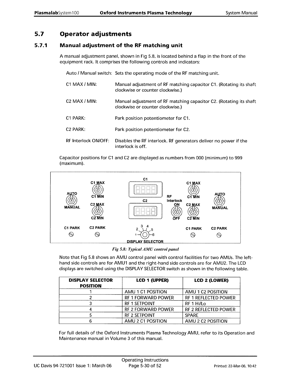
A manual
adjustment
panel, shown in Fig 5.8,
is
located
behind
a
flap
in
the
front
of
the
equipment
rack.
It
comprises
the
following
controls and indicators:
Auto
/
Manual
switch: Sets
the
operating
mode
of
the
RF
matching
unit.
C1
MAX
/ MIN:
Manual
adjustment
of
RF
matching
capacitor
C1.
(Rotating its
shaft
clockwise
or
counter
clockwise.)
C2
MAX
/ MIN:
Manual
adjustment
of
RF
matching
capacitor
C2.
(Rotating its
shaft
clockwise
or
counter
clockwise.)
C1
PARK:
Park position
potentiometer
for
C1.
C2
PARK:
Park
position
potentiometer
for
C2.
RF
Interlock
ON/OFF: Disables
the
RF
interlock.
RF
generators
deliver
no
power
if
the
interlock
is
off.
Capacitor positions
for
C1
and
C2
are displayed
as
numbers
from
000
(minimum)
to
999
(maximum).
C1
:i
:i
ti
ti
C1
IN
RF
C1
IN
C2
Interlock
CI
ON
CI
MANUAL
~
MANUAL
C2
IN
C2
IN
C1
PARK
C2 PARK
3 4
C1
PARK
C2 PARK
2-<:Q}
@
@
1 0 6
@
@
R
Fig 5.8: Typical
AMU
control
panel
Note
that
Fig
5.8 shows an
AMU
control
panel
with
control
facilities
for
two
AMUs. The
left-
hand side controls are
for
AMU1 and
the
right-hand
side controls are
for
AMU2. The
LCD
displays are switched using
the
DISPLAY
SELECTOR
switch
as
shown
in
the
following
table.
DISPLAY SELECTOR LCD 1 (UPPER) LCD 2 (LOWER)
POSITION
1
AMU
1
C1
POSITION
AMU
1
C2
POSITION
2
RF
1 FORWARD
POWER
RF
1
REFLECTED
POWER
3
RF
1
SETPOINT
RF
1
Hillo
4
RF
2 FORWARD
POWER
RF
2
REFLECTED
POWER
5
RF
2
SETPOINT
SPARE
6
AMU
2
C1
POSITION
AMU
2
C2
POSITION
For
full
details
of
the
Oxford
Instruments Plasma Technology AMU,
refer
to
its
Operation
and
Maintenance
manual
in
Volume
3
of
this manual.
UC
Davis 94-721001
Issue
1:
March 06
Operating
Instructions
Page 5-30
of
52
Printed: 22-Mar-06, 10:42
System
Manual
Oxford
Instruments
Plasma
Technology
PlasmalabSystem
100
5.7.2
Adjusting
the
nitrogen
regulator
outlet
pressure
NOTE:
Refer
to
Section 2
for
a description
of
the
Nitrogen
vent
distribution
circuit.
The
regulator
outlet
pressure should
not
usually
require
adjustment
from
its
factory
setting.
However,
if
adjustment
is
necessary, proceed
as
follows.
WARNING
THIS PROCEDURE INVOLVES WORKING ON THE SYSTEM WITH COVERS REMOVED
AND
WITH THE ELECTRICAL POWER ON. THEREFORE IT MUST ONLY
BE
CARRIED OUT
BY TRAINED
AND
COMPETENT PERSONNEL
WHO
ARE AWARE
OF
THE RISKS
INVOLVED.
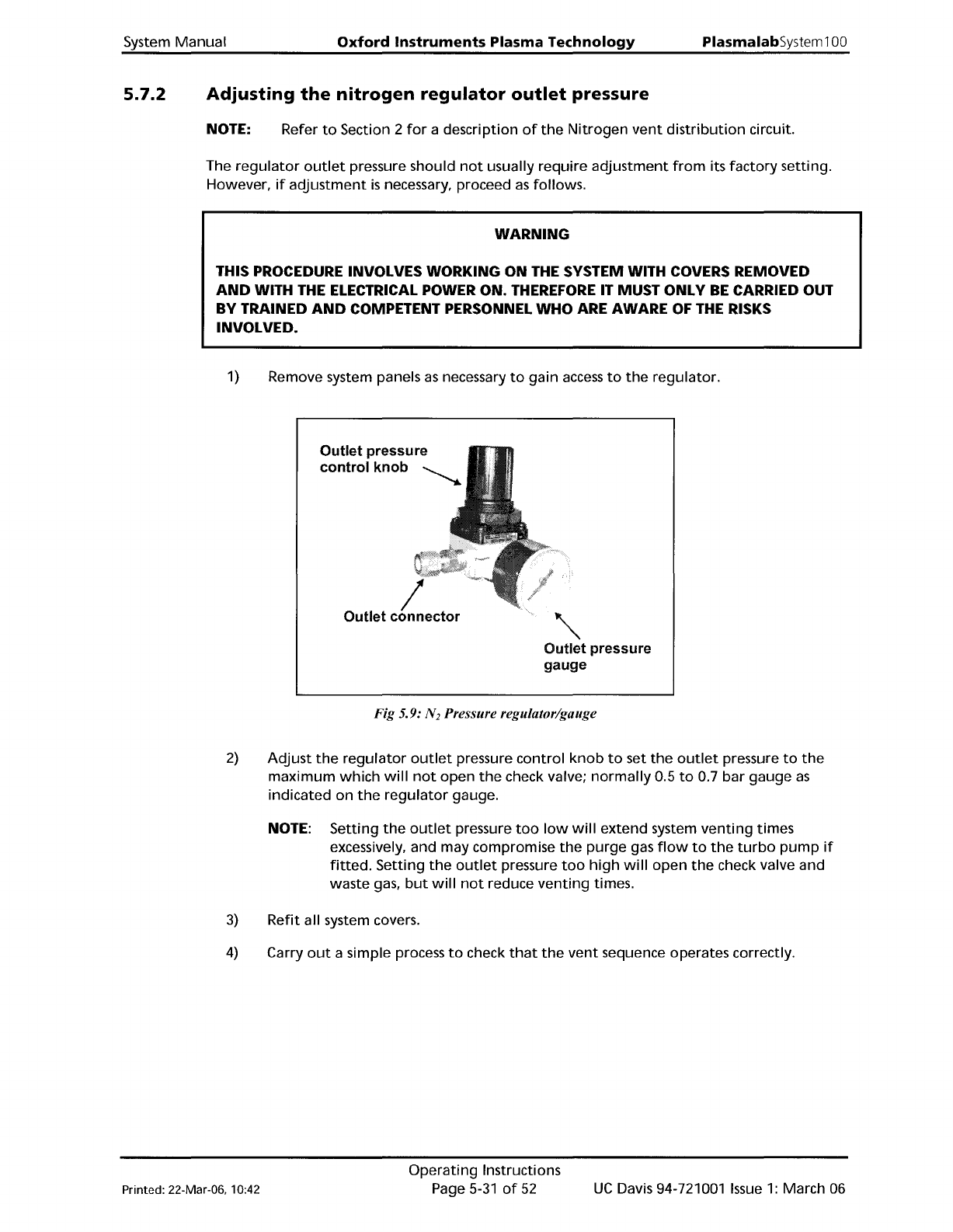
1)
Remove system panels
as
necessary
to
gain
access
to
the
regulator.
Outlet
pressure
control
knob
~
/
Outlet
connector
'"
Outlet
pressure
gauge
Fig 5.9: N
2
Pressure regulator/gauge
2)
Adjust
the
regulator
outlet
pressure
control
knob
to
set
the
outlet
pressure
to
the
maximum
which
will
not
open
the
check valve;
normally
0.5
to
0.7
bar
gauge
as
indicated
on
the
regulator
gauge.
NOTE: Setting
the
outlet
pressure
too
low
will
extend
system
venting
times
excessively, and may compromise
the
purge
gas
flow
to
the
turbo
pump
if
fitted.
Setting
the
outlet
pressure
too
high
will
open
the
check valve and
waste gas,
but
will
not
reduce
venting
times.
3)
Refit
all system covers.
4)
Carry
out
a simple process
to
check
that
the
vent
sequence operates correctly.
Printed: 22-Mar-06, 10:42
Operating
Instructions
Page
5-31
of
52
UC
Davis 94-721001
Issue
1:
March 06
PlasmalabSystem100
Oxford
Instruments
Plasma Technology
System Manual
5.7.3
Rotary/dry
pump
N
z
purge
flow
rate
adjustment
CAUTION
If
the
rotary/dry
pump's
N
z
purge
flow
rate
is
inadequate,
damage
to
the
pump
could occur.
Ensure
that
the
flow
rate
is
set
to
the
value
recommended
by
the
pump
manufacturer.
The
rotary/dry
pump's
N
z
purge
flow
rate
is
set
at
the
factory
before
system
shipment
and
should
not
need adjustment. However,
the
pump
purge
rate
will
need
to
be
confirmed
on
installation
and
at
any
time
the
purge
gas supply pressure changes significantly.
If
adjustment
is
necessary,
refer
to
Appendix
R in this manual.
UC
Davis 94-721001
Issue
1:
March 06
Operating
Instructions
Page 5-32
of
52
Printed: 22-Mar-06. 10:42