Oxford-100-Manual.pdf - 第41页
System Manual Oxford Instruments Plasma Technology Plasma lab System 100 3.3.4 Interlocks There are two types of interlocks used on the Plasma lab System 100, hardware and software. In all areas, the hardware interlock w…
Plasma
lab
System
100
Oxford
Instruments
Plasma
Technology
System Manual
LF GENERATOR
RF GENERATOR
ROUGHING VALVE
~
WAFERLIFT
GAS POD CONTROL
TURBO PURGE VALVE
PENNING/PIRANI PRESSURE GAUGE
AUTOMATIC PRESSURE CONTROLLER
CHAMBER VENT VALVE
HEATER CONTROLLER
CONTROL & STATUS SIGNALS
<E--
END POINT
<E--
CM PRESSURE GAUGE
<E--
WATER FLOW SWITCH INTERLOCKS
~
TURBO CONTROLLER
~
TURBO BACKING VALVE
1------------------------
I
I
I
I
I
I
I
I
I
I
I
I
I
I
I
I
I
I
I
I
I
I
I
I
I
I
I
I
I
~
CM GAUGE ISOLATION VALVE
<:J
C>
~
GATE VALVE
<E--
CHAMBER LID INTERLOCK
<E--
VACSTAT (CHAMBER)
<E--
CHAMBER THERMOCOUPLE
~
GENERATOR INTERLOCK
~
LOAD
LOCK
VENT VALVE
~
LOAD
LOCK
TURBO PURGE VALVE
~
LOAD
LOCK
ROUGHING VALVE
~
LOAD
LOCK
TURBO BACKING VALVE
<E--
LOAD
LOCK
SLIT VALVE OPEN
<E--
LOAD
LOCK
SLIT VALVE CLOSED
<E--
LOAD
LOCK
LID OPEN INTERLOCK
<E--
LOAD
LOCK
LID CLOSED
<E--
EMO BUTTON IN
<E--
PUMPS
<E--
LOADING ARM HOME
PERSONAL
COMPUTER
RUNNING
'PC 2000'
SOFTWARE
ARCNET
SERIAL DIGITAL
COMMUNICATIONS
PLC
INTERFACE
- - - - -
PCB
MEA
-
PL1
- - -
--
MAEB
-
PL2
- - -
--
PEA 1
-
J8
- - -
--
PEA 2
-
J9
- - - - -
PEA 3 -
J10
- - - - -
CPU
- - -
--
PEA 4
-
J11
- - -
--
NT/PS
JY
BATTERY
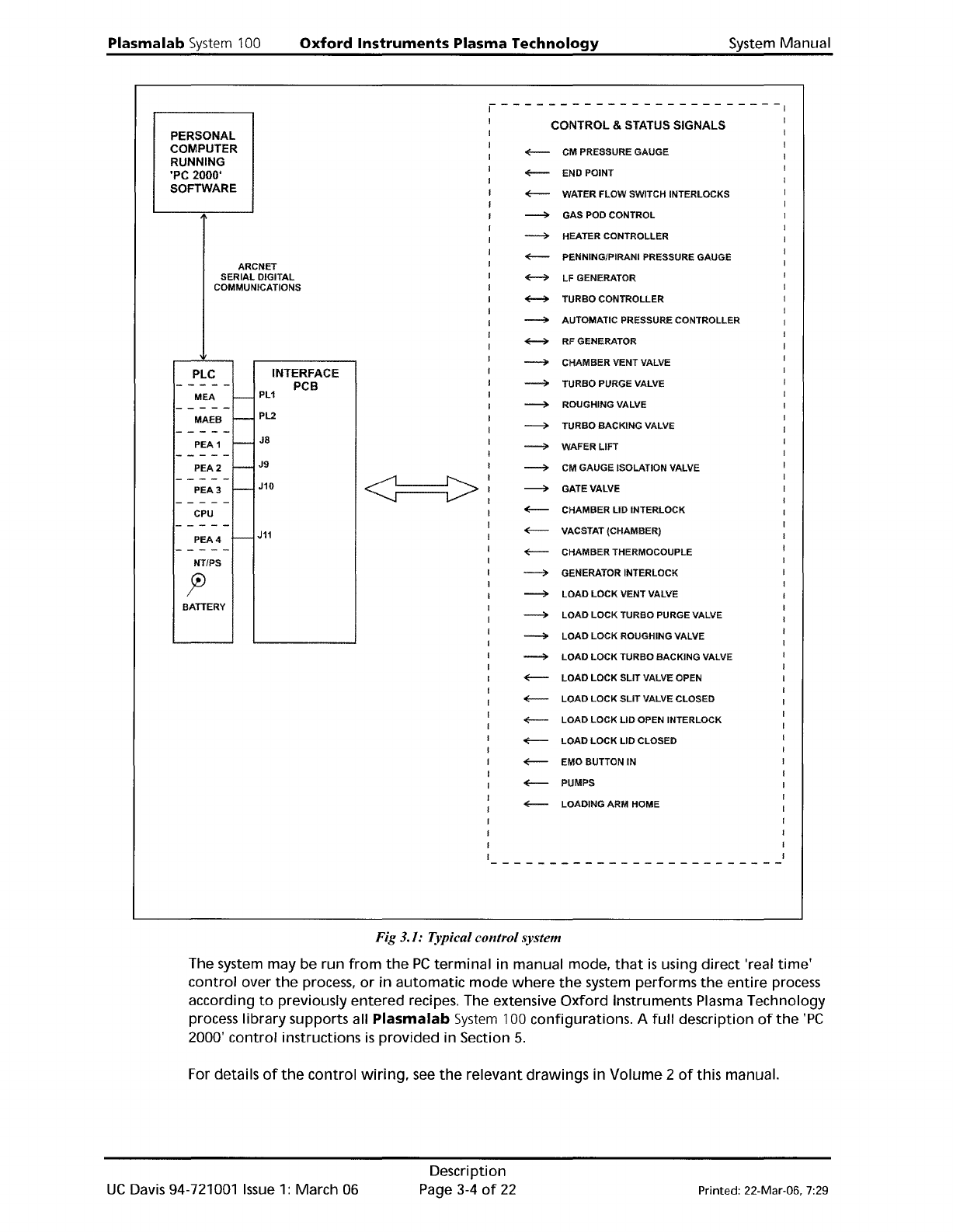
Fig 3.1: Typical control system
The system may be run
from
the
PC
terminal
in manual mode,
that
is
using direct 'real
time'
control
over
the
process,
or
in
automatic
mode
where
the
system performs
the
entire
process
according
to
previously
entered
recipes. The extensive
Oxford
Instruments Plasma Technology
process library supports all
Plasma
lab
System
100 configurations. A
full
description
of
the
'PC
2000'
control
instructions
is
provided in Section
5.
For details
of
the
control
wiring,
see
the
relevant drawings in Volume 2
of
this manual.
UC
Davis 94-721001
Issue
1:
March 06
Description
Page 3-4
of
22 Printed: 22-Mar-06, 7:29
System
Manual
Oxford
Instruments
Plasma
Technology
Plasma
lab
System
100
3.3.4
Interlocks
There are
two
types
of
interlocks used
on
the
Plasma
lab
System
100,
hardware
and software.
In
all areas,
the
hardware
interlock
will
override
any
software
interlock. The
hardware
interlocks, and
their
effect
on
the
system components
in
the
case
of
an
interlock
becoming
open circuit are
as
follows:
The electrical interlocks are divided
into
two
circuits
controlling
the
power
to
the
system.
1)
The mains
power
connection
is
made
to
a system Power
Distribution
Unit.
The Power
Distribution
Unit
will
disable all
of
its
power
outputs
under
the
following
conditions:
a)
If
the
Emergency
Off
button
is
pressed.
b)
If
there
is
an
interruption
of
the
power
input
to
the
system.
c)
If
the
Power
Distribution
Unit
external
facility
interlock
sensor
link
becomes
open circuit.
NOTE: The Power
Distribution
Unit
external
facility
interlock
sensor
link
enables
the
interlocks
of
external sensors, e.g. gas
detectors, exhaust scrubbers, etc.,
to
be
monitored
by
the
Power
Distribution
Unit. External
interlock
contacts connected
to
this
link
should
be
Normally
Closed, i.e.
faulting
to
an Open Circuit.
2)
The system
internal
24V supply, comprises a process line, a chamber lid line and a
water
flow
switch
(where
fitted):
The 24V process line, which controls
the
process gases and plasma
power
supply
units,
will
be disabled
if
the
Vacuum Safety Switch
is
open circuit, i.e. Chamber
Pressure> 600 mbar.
The 24V chamber
lid
line
will
be disabled
if
the
chamber lid
is
OPEN,
leaving
the
system
controller
operational,
but
disabling all system components.
Printed: 22-Mar-06, 7:29
Description
Page 3-5
of
22
UC
Davis 94-721001
Issue
1: March 06
Plasma
lab
System
100
Oxford
Instruments
Plasma
Technology
System Manual
Emergency
Off
I Electrical
24V
Process
line
24V
Chamber
lid
line
Fail
Interlock
Fail
Restore
Fail
Restore
Fail Restore
System/Controller
OFF
Restart
Required
ON
ON
RF
Generator
OFF
Powered, NOT
OFF
Powered,
OFF
Powered, NOT
active
NOT active
active
Process
Gases
OFF
Powered, NOT
OFF
Powered,
OFF
Powered, NOT
active NOT active
active
Automatic
**
Pressure
CLOSED CLOSED
NO
NO
CLOSED CLOSED
Controller
Valve CHANGE
CHANGE
Load lock
*
Slit Valve HOLD
HOLD
HOLD HOLD
HOLD HOLD
Pumps
OFF
Pumps
must
be
NO
NO
OFF
Pumps must
restarted CHANGE
CHANGE
be restarted
*
If
closed, stays closed.
If
open,
will
stay open
until
the
loadinq
arm
is
at
its
home
position;
then
it
will
close.
**
If
'high
pressure'
is
signalled
during
process,
APC
opens and process step aborts. High pressure
at
other
times does
not
alter
the
APC.
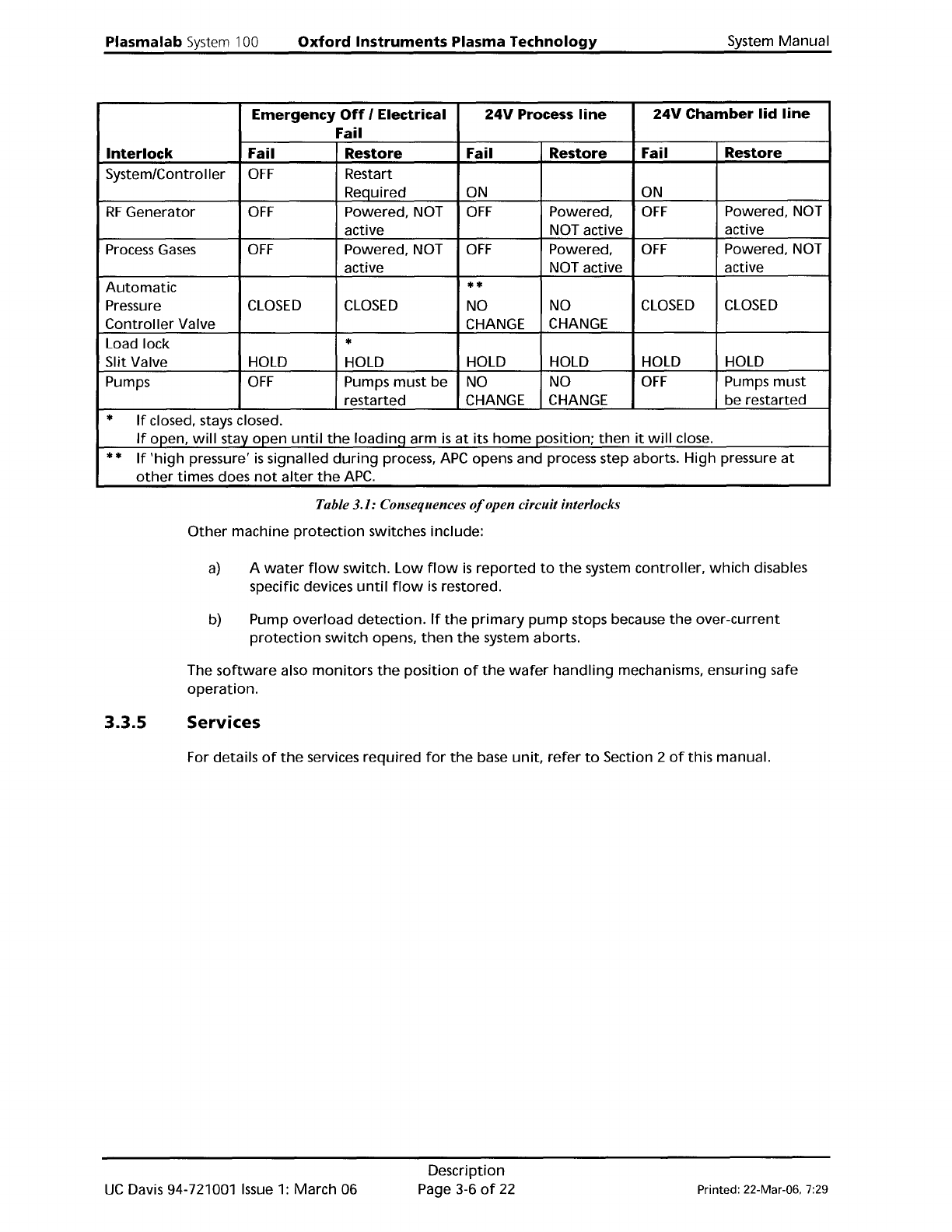
Table 3.1: Consequences
%pen
circuit interlocks
Other
machine
protection
switches include:
a)
A
water
flow
switch.
Low
flow
is
reported
to
the
system controller,
which
disables
specific devices
until
flow
is
restored.
b) Pump
overload
detection.
If
the
primary
pump
stops because
the
over-current
protection
switch opens,
then
the
system aborts.
The
software
also
monitors
the
position
of
the
wafer
handling
mechanisms, ensuring safe
operation.
3.3.5
Services
For details
of
the
services
required
for
the
base
unit,
refer
to
Section 2
of
this manual.
UC
Davis 94-721001
Issue
1:
March 06
Description
Page 3-6
of
22
Printed: 22-Mar-06, 7:29