Oxford-100-Manual.pdf - 第44页
Plasmalab System 100 Oxford Instruments Plasma Technology System Manual 3.4.1 3.4.2 94-100-3-00/21P Process chamber electrical heating kit The electrical heating kit comprises four cartridge heaters; inserted into holes …
System
Manual
Oxford
Instruments
Plasma
Technology
Plasma
lab
System
100
3.4
94·100·3·41C
ICP
180
chamber
kit
with
gate
valve
The
ICP
chamber
kit
comprises
the
following
components:
Process
chamber.
Pumping
port
isolation valve and
automatic
pressure
controller
suitable
for
use
with
a
turbomolecular
pump.
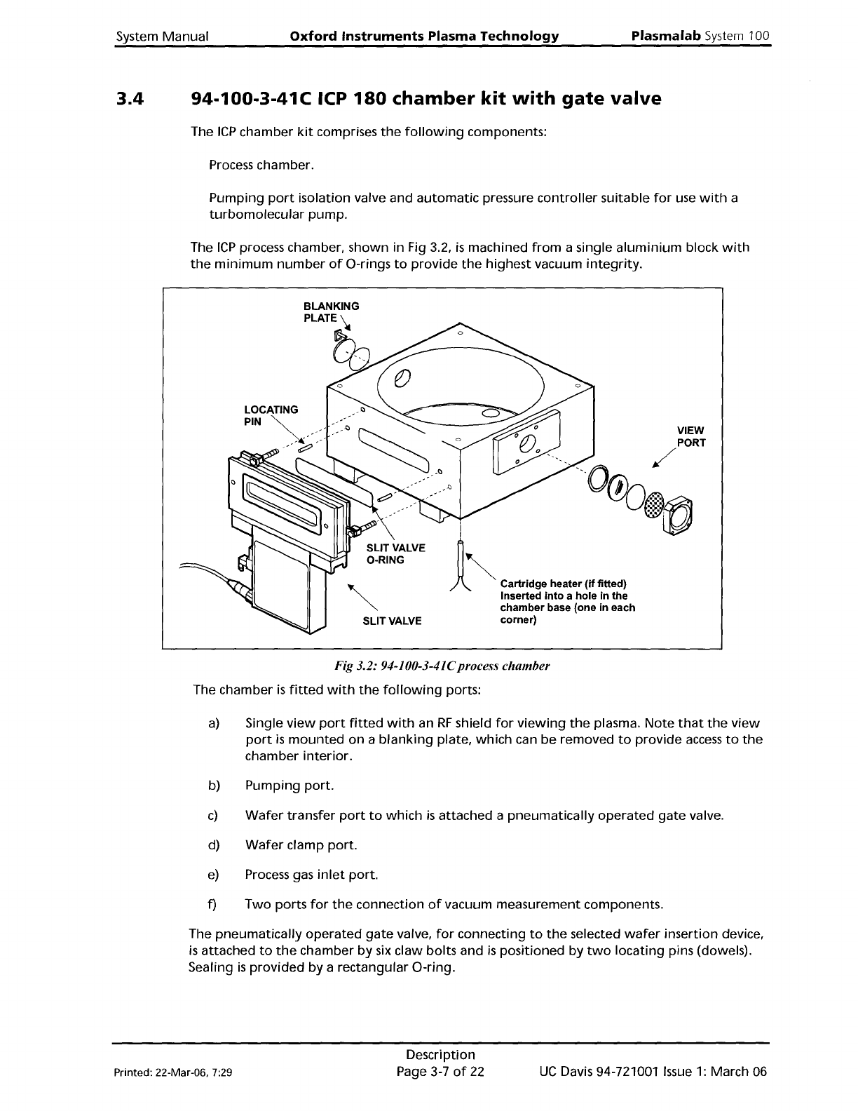
The
ICP
process chamber, shown
in
Fig 3.2,
is
machined
from
a single
aluminium
block
with
the
minimum
number
of
O-rings
to
provide
the
highest vacuum
integrity.
LOCATING
SLIT
VALVE
!
1
~
C''''''g
......
,
(0
fltted)
Inserted
into
a hole in the
chamber base (one in each
corner)
VIEW
Fig 3.2: 94-100-3-41Cprocess
chamber
The chamber
is
fitted
with
the
following
ports:
a)
Single
view
port
fitted
with
an
RF
shield
for
viewing
the
plasma.
Note
that
the
view
port
is
mounted
on
a
blanking
plate,
which
can
be
removed
to
provide
access
to
the
chamber
interior.
b) Pumping
port.
c)
Wafer
transfer
port
to
which
is
attached a
pneumatically
operated
gate
valve.
d)
Wafer
clamp
port.
e)
Process gas
inlet
port.
f)
Two
ports
for
the
connection
of
vacuum measurement components.
The
pneumatically
operated
gate
valve,
for
connecting
to
the
selected
wafer
insertion device,
is
attached
to
the
chamber
by
six claw
bolts
and
is
positioned by
two
locating
pins (dowels).
Sealing
is
provided
by
a rectangular O-ring.
Printed: 22-Mar-06, 7:29
Description
Page 3-7
of
22
UC
Davis 94-721001
Issue
1: March 06
Plasmalab
System
100
Oxford
Instruments
Plasma
Technology
System
Manual
3.4.1
3.4.2
94-100-3-00/21P
Process
chamber
electrical
heating
kit
The electrical
heating
kit
comprises
four
cartridge
heaters; inserted
into
holes
at
the
corners
in
the
base
of
the
process chamber,
see
Fig 3.2. Heater
control
is
via a
unit
mounted
on
the
console,
where
the
temperature
can
be
set manually. A
temperature
in
the
range 50°C
to
60°C
is
recommended
for
most
processes.
WARNING
IF THE PROCESS CHAMBER TEMPERATURE IS
SET
TO A VALUE ABOVE
GOGC,
CONTACT
WITH IT
CAN
CAUSE BURNS.
BEFORE OPERATING THE CHAMBER ABOVE
GOGC,
ENSURE THAT EXTERNAL HEAT
SHIELDS ARE FITTED.
94-100-3-00/05
200mm
Pumpdown
pipe
heater
kit
This
heating
kit
is
applied
to
the
pump-down
pipe
to
give
optimum
vacuum performance and
to
minimise
the
deposition
of
loosely
adherent
material,
which
might
generate
particulates.
UC
Davis 94-721001
Issue
1:
March
06
Description
Page 3-8
of
22
Printed: 22-Mar-06, 7:29
System
Manual
Oxford
Instruments
Plasma
Technology
Plasma
lab
System
100
3.5
94-100-5-12A
Cryo /
heated
-150/400C
helium-assisted
lower
electrode
The helium-assisted
lower
electrode, shown in Fig 3.3,
is
fabricated
from
aluminium.
The
electrode
is
fitted
with
an
integral
dark
space shield.
The
lower
electrode
is
heated by an
embedded
12S0W
element
and cooled by
liquid
nitrogen
flowing
through
embedded
tUbing.
Wafer
lift
The
wafer
is
lifted
clear
of
the
table
(1Smm)
for
transferring
into
a load lock
or
transfer
chamber
by
the
wafer
lift
assembly. Compressed
air
flowing
into
the
air cylinder forces its
piston and
plunger
upwards. The
plunger
contacts
the
base
of
the
bellows
which
is
connected
to
a push rod. The 3-pin
wafer
support,
mounted
on
top
of
the
push rod, rises
lifting
the
wafer
clear
of
the
table. The push
rod
is
lowered
by
the
force
exerted
by
the
return
spring.
Wafer
clamp
The
wafer
clamp comprises a clamping
ring
attached
to
a
lifting
mechanism, and a clamping
plate. The clamping plate, attached
to
the
clamping
ring
via
three
pillars and screws,
comprises an
aluminium
annulus
with
a
quartz
circular insert.
The
wafer
clamp
is
raised and
lowered
by
two
air cylinders,
attached
to
the
outside
of
the
process chamber;
one
located
at
each side
of
the
wafer
clamp. The piston
of
each air cylinder
is
attached
to
a push rod,
which
passes
through
the
base
of
the
process chamber.
Within
the
process chamber, a circular
plate
mounted
on
the
top
of
the
push rod,
is
attached
to
the
wafer
clamp
by
three
MS
setscrews and compression springs.
Rotating
the
setscrews changes
the
compression
of
the
springs and consequently
the
clamping
force
exerted
on
the
wafer.
See
Section 6
for
the
clamping force
adjustment
procedure.
Note
that
clamping plates are available
with
inserts
for
various sized wafers. Before
loading
a
wafer
into
the
process chamber, ensure
that
the
correct clamping
plate
is
fitted.
See
Section 6
for
the
clamping
plate
changeover procedure.
Table
top
plate
In some systems,
the
table
top
plate
is
fixed
to
the
table
by
a
ring
of
cap-head bolts.
If
your
system has a
table
of
this type,
refer
to
the
following
text
and note.
The
bolt
heads are concealed
behind
screw covers,
which
require
a special
tool
(supplied
with
the
system)
for
removal. (Tool
part
number:
MD91 D21726.)
NOTES:
1)
When
re-fixing
the
table
top,
do
not
over-tighten
the
bolts
which
will
cause
the
table
top
to
bow.
Check
with
a
straight
edge
after
tightening:
if
the
table
top
is
not
flat,
release
the
bolt
tensions
until
it
is.
2)
The screw covers (MD91 D21723) are
aluminium.
When
removing
the
covers,
it
is
recommended
to
use a
little
iso-propyl alcohol (lPA)
to
prevent
the
thread
fromjamming.
Helium
backing
The purpose
of
helium
backing
is
to
set
the
temperature
of
the
wafer
close
to
that
of
the
temperature-controlled
table
by
heat
transfer. Helium
is
fed
from
a
number
of
small holes in
the
table
underneath
the
wafer
(which
is
clamped
to
the
table)
from
where
it
flows
radially
Printed: 22-Mar-06. 7:29
Description
Page 3-9
of
22
UC
Davis 94-721001
Issue
1: March 06