Oxford-100-Manual.pdf - 第63页
System Manual Oxford Instruments Plasma Technology Plasma lab System 100 4.2.3.1 Connecting the 3-phase supply cable to the power box If it is necessary to connect the 3-phase supply cable to the power box, use the follo…
Plasma
lab
System
100
Oxford
Instruments
Plasma
Technology
System
Manual
4.2.3
4)
Transport
the
rotary
vane
pump
to
the
grey area and
mount
it
in
the
required
position
in accordance
with
the
pump
manufacturer's instructions. Refer
to
the
manufacturer's
literature
in
Volume
3
of
this manual.
Connecting
the
services
IMPORTANT
NOTES
(A)
BEFORE
CONNECTING
ANY
OF
THE SERVICES, ENSURE THAT
THEY ARE TURNED OFF. E.G. COMPRESSED
AIR
AND
GAS
SUPPLY VALVES
SET
TO THEIR
OFF
POSITIONS
AND
ELECTRICAL
SUPPLIES SWITCHED
OFF
AND
LOCKED OUT.
(B) DO NOT RESTRICT ACCESS TO
THE
EMERGENCY
OFF
SWITCH
(EMO
CONTROL) BY LOCATING CABLES
AND
OTHER
OBSTACLES
IN
FRONT
OF
THE
SYSTEM.
(C)
DO
NOT LOCATE CABLES WHERE PERSONNEL ARE LIABLE TO
WALK. OIPT RECOMMENDS THAT CABLES ARE LOCATED
IN
CABLE TRUNKING I TRENCHES.
1)
Connect
the
extraction
collars
on
the
process chamber(s) (e.g.
ICP
process chambers)
and
the
gas
pod
to
the
appropriate
extraction
systems.
2)
Connect
the
rotary
vane
pump
exhaust line.
3)
Connect
the
Nitrogen
purge
lines
to
the
system services panel(s) and
the
rotary
vane
pump.
4)
Connect
the
compressed air supply
to
the
system services panel(s) and
to
the
gas
pod.
5)
Connect
the
gas supplies
to
the
gas
pod
(all
gas
supply valves closed).
6)
Connect
the
gas
outlet
line,
control
cable and
earth
cable
(see
Fig 4.1)
from
the
gas
pod
to
the
system console.
7)
Connect
the
cooling
circuits
to
the
system console.
8)
At
the
system
PC,
connect
the
monitor,
keyboard and mouse.
then
connect
the
control
cable(s)
from
the
PC
to
the
system console.
9)
Connect
the
electrical supply
from
the
safety isolation box
to
the
system console.
If
it
is
necessary
to
connect
the
3-phase electrical supply cable
to
the
power
box,
refer
to
sub-section 4.2.3.1.
10) Connect
the
electrical supply
to
the
PC.
11) Ensure
that
all covers and panels are
fitted
and attach notices
to
the
system
indicating
that
the
system
is
not
ready
for
service.
Installation
is
now
complete
and
the
system
is
ready
for
commissioning by
GIPT.
Note
that
customers
who
have arranged
to
commission
the
system themselves can
ignore
the
remainder
of
this Section.
12)
Complete
and sign
the
'System Readiness'
form
QCF
89 (shipped
with
the
system).
then
fax
it
to
GIPT
who
will
arrange
for
the
system
to
be commissioned.
Issue
4:
March 05
Installation and Commissioning
Page 4-4
of
8
Printed: 16
March
2006
11
:59
System
Manual
Oxford
Instruments Plasma Technology
Plasma
lab
System
100
4.2.3.1
Connecting
the
3-phase
supply
cable
to
the
power
box
If
it
is
necessary
to
connect
the
3-phase supply cable
to
the
power
box, use
the
following
steps.
1)
Ensure
that
the
supply cable
is
not
connected
to
the
safety isolation box.
2)
Remove
the
power
box
cover.
3)
Inside
the
power
box, remove
the
clear plastic safety cover
from
the
power
box
(secured
to
the
right-hand
side
of
the
power
box
by
four
screws).
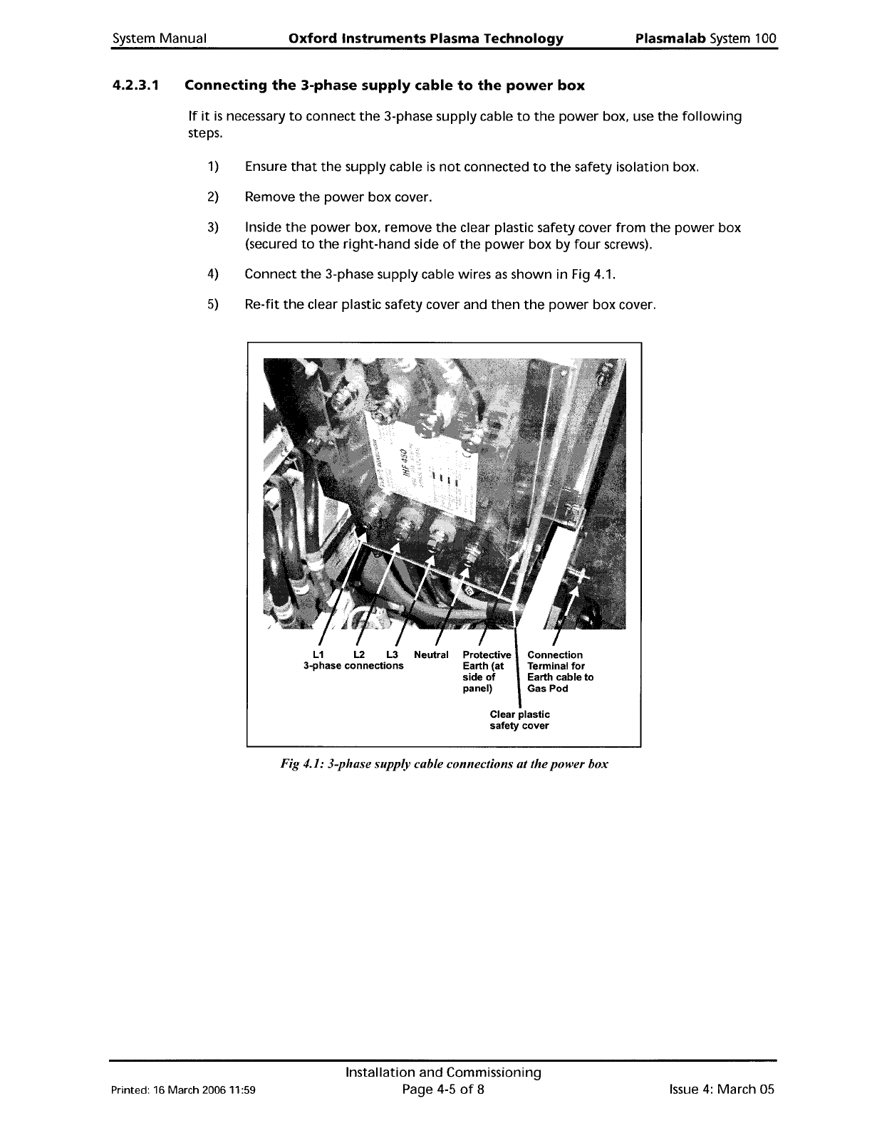
4)
Connect
the
3-phase supply cable wires
as
shown
in Fig 4.1.
5)
Re-fit
the
clear plastic safety cover and
then
the
power
box cover.
L1 L2 L3 Neutral Protective
3-phase
connections
Earth (at
side
of
panel)
Connection
Terminal
for
Earth cable
to
Gas
Pod
Printed: 16 March 200611:59
Clear
plastic
safety
cover
Fig 4.1: 3-phase supply cable connections atthepower box
Installation and Commissioning
Page 4-5
of
8
Issue
4:
March 05
Plasma
lab
System
100
Oxford
Instruments
Plasma Technology System Manual
4.3
Commissioning
the
system
Commissioning
of
the
system
will
be carried
out
by
OIPT
in accordance
with
their
standard
procedures and any
additional
requirements stated in
the
sales contract. Generally, this
will
include
the
following
items:
1)
Checking
that
the
installation
has been carried
out
satisfactorily.
2)
Powering
up
the
system.
3)
Checking
the
operation
of
the
system,
including
the
Emergency
Off
facility
and all
interlocks.
4)
Ensuring
that
the
system can
perform
the
processes specified in
the
sales
contract.
5)
Providing
training
on
the
system.
4.4
System
adjustments
This sub-section gives details
of
adjustments
which
may be necessary
depending
on system
configuration.
In
addition
to
these adjustments,
refer
to
the
Operator
Adjustments sub-
section
in
Section 5
(Operating
Instructions)
of
this manual.
4.4.1
4.4.2
Heater/Chillers
If
your
Plasmalab system has a
remote
Betta-Tech heater/chiller, e.g.
CUSOO,
with
a Eurotherm
Controller,
please
note
the
following.
The
Eurotherm
controller
has a
default
temperature
setpoint. For
the
system
to
operate
correctly, this
setpoint
must be set
to
a
temperature
suitable
for
the
system and
coolant
used.
For example,
if
the
coolant
is
water,
do
not
set
the
setpoint
to
0°
C
or
below.
Check
the
setpoint
before
using
the
system and
if
necessary change
it
in accordance
with
the
instructions given in
the
Eurotherm Controller's manual.
Process
pump
purge
An
inert
gas,
normally
nitrogen,
is
added
to
the
process chamber
primary
mechanical
pump
for
a
variety
of
reasons:
a)
When
pumping
condensable vapours,
it
is
flowed
via
the
gas ballast port. This helps
to
prevent
condensation
during
compression, and reduces
the
amount
of
liquids
such
as
water
vapour
or
SiCI
4
in
the
pump
fluid.
b)
When
pumping
reactive
gases,
it
is
bubbled
through
the
pump
fluid,
to
help
drive
out
acidic compounds.
c)
When
pumping
flammable
or
explosive
gases,
it
is
added
to
dilute
the
gas
below
the
threshold
for
explosion.
d) In
dry
pumps,
the
purge
gas
flow
is
important
for
managing
heat
and
limiting
particle
build
up.
WARNING
DILUTION IS NOT USED
TO
MAKE
THE
EXHUAST
SAFE
TO
BREATH: IT MUST
STILL
BE
DUeTED
AWAY
AND
TREATED APPROPRIATELY.
Issue
4:
March
OS
Installation and Commissioning
Page 4-6
of
8
Printed: 16 March 2006
11
:59