Oxford-100-Manual.pdf - 第113页
System Manual Oxford Instruments Plasma Technology PlasmalabSystem 100 5.8.7 Mass flow calibration page Fig 5.18: Massjlow calibration page CAUTION Some gas mixtures may produce particles in the chamber or gas lines. Che…
PlasmalabSystem100
Oxford
Instruments
Plasma
Technology
System Manual
Transfer status/
Log
Comment
message
field
Wafer
status
field
Log
Comment
button
Return
to
Process
button
Start
button
Stop
button
Recipe message
field
Step
Time
fields
Log
Interval
fields
Pump
to
Pressure
checkbox
Pressure fields
Pump
to
time
checkbox
Pump
Time
Gas
pod
and
process chamber
mimic
Mass
Flow
Calibration
button
NOTE:
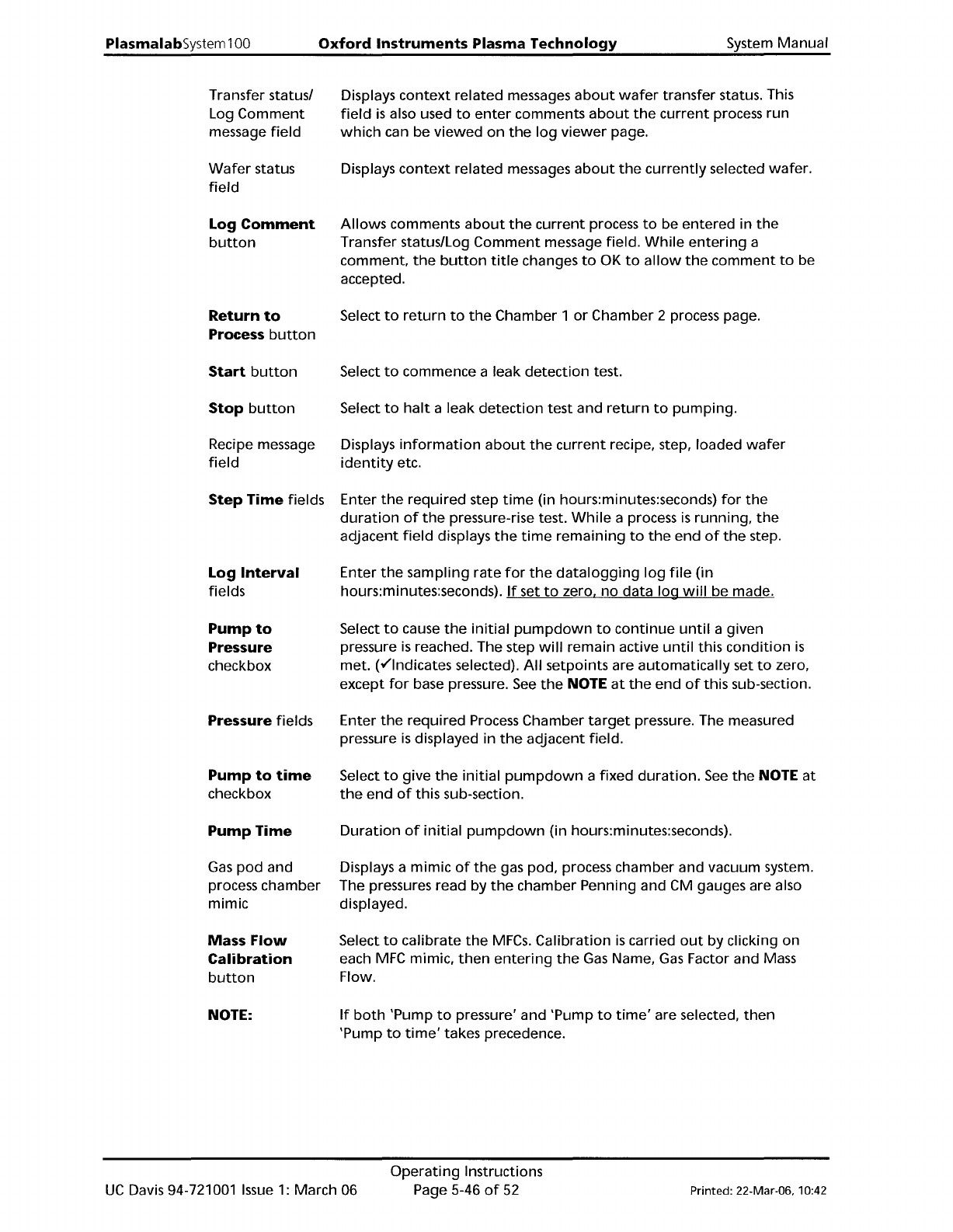
Displays
context
related messages
about
wafer
transfer status. This
field
is
also used
to
enter
comments
about
the
current
process run
which
can be viewed
on
the
log
viewer
page.
Displays
context
related messages
about
the
currently
selected wafer.
Allows
comments
about
the
current
process
to
be entered in
the
Transfer status/Log
Comment
message field.
While
entering
a
comment,
the
button
title
changes
to
OK
to
allow
the
comment
to
be
accepted.
Select
to
return
to
the
Chamber 1
or
Chamber 2 process page.
Select
to
commence a leak
detection
test.
Select
to
halt
a leak
detection
test and
return
to
pumping.
Displays
information
about
the
current
recipe, step, loaded
wafer
identity
etc.
Enter
the
required
step
time
(in hours:minutes:seconds)
for
the
duration
of
the
pressure-rise test.
While
a process
is
running,
the
adjacent
field
displays
the
time
remaining
to
the
end
of
the
step.
Enter
the
sampling
rate
for
the
data
logging
log
file
(in
hours:minutes:seconds).
If
set
to
zero,
no
data log
will
be made.
Select
to
cause
the
initial
pumpdown
to
continue
until
a given
pressure
is
reached. The step
will
remain active
until
this
condition
is
met. (v"lndicates selected).
All
setpoints are
automatically
set
to
zero,
except
for
base pressure.
See
the
NOTE
at
the
end
of
this sub-section.
Enter
the
required
Process Chamber
target
pressure. The measured
pressure
is
displayed in
the
adjacent field.
Select
to
give
the
initial
pumpdown
a
fixed
duration.
See
the
NOTE
at
the
end
of
this sub-section.
Duration
of
initial
pumpdown
(in hours:minutes:seconds).
Displays a
mimic
of
the
gas pod, process chamber and vacuum system.
The pressures read by
the
chamber Penning and CM gauges are also
displayed.
Select
to
calibrate
the
MFCs.
Calibration
is
carried
out
by clicking on
each
MFC
mimic,
then
entering
the
Gas
Name,
Gas
Factor and Mass
Flow.
If
both
'Pump
to
pressure' and 'Pump
to
time'
are selected,
then
'Pump
to
time'
takes precedence.
UC
Davis 94-721001
Issue
1:
March 06
Operating
Instructions
Page 5-46
of
52
Printed: 22-Mar-06. 10:42
System
Manual
Oxford
Instruments
Plasma
Technology
PlasmalabSystem
100
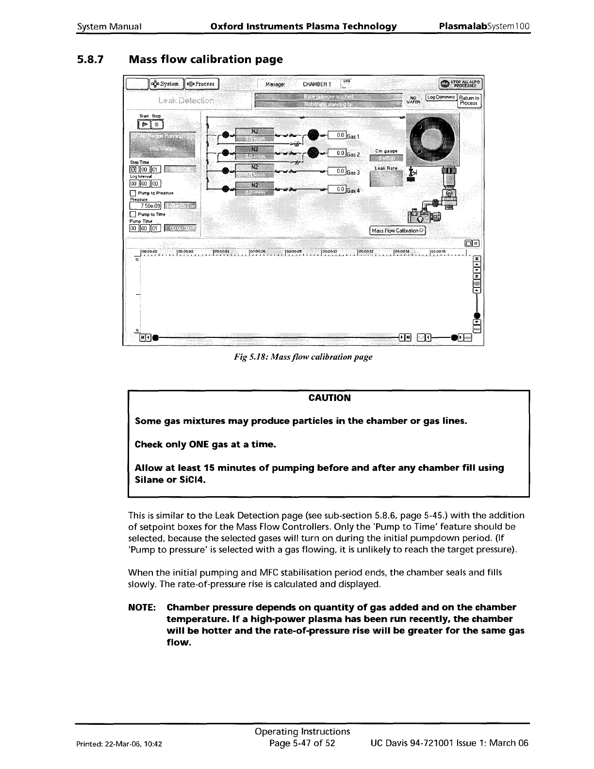
5.8.7
Mass
flow
calibration
page
Fig 5.18:
Massjlow
calibration page
CAUTION
Some
gas
mixtures
may
produce
particles
in
the
chamber
or
gas lines.
Check
only
ONE gas
at
a
time.
Allow
at
least
15
minutes
of
pumping
before
and
after
any
chamber
fill
using
Silane
or
SiCI4.
This
is
similar
to
the
Leak Detection page
(see
sub-section 5.8.6, page 5-45.)
with
the
addition
of
setpoint
boxes
for
the
Mass Flow Controllers.
Only
the
'Pump
to
Time'
feature
should be
selected, because
the
selected gases
will
turn
on
during
the
initial
pumpdown
period.
(If
'Pump
to
pressure'
is
selected
with
a gas
flowing,
it
is
unlikely
to
reach
the
target
pressure).
When
the
initial
pumping
and
MFC
stabilisation
period
ends,
the
chamber seals and fills
slowly. The rate-of-pressure rise
is
calculated and displayed.
NOTE:
Chamber
pressure
depends
on
quantity
of
gas
added
and
on
the
chamber
temperature.
If
a
high-power
plasma
has
been
run
recently,
the
chamber
will
be
hotter
and
the
rate-of-pressure
rise
will
be
greater
for
the
same
gas
flow.
Printed: 22-Mar-06. 10:42
Operating
Instructions
Page 5-47
of
52
UC
Davis 94-721001
Issue
1:
March 06
PiasmaiabSystem100
Oxford
Instruments
Plasma Technology
System Manual
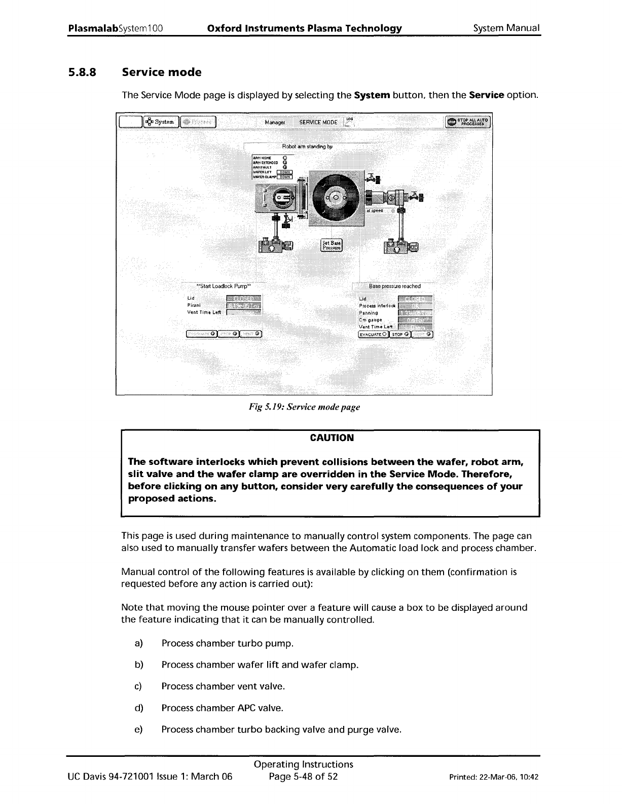
5.8.8
Service
mode
The Service
Mode
page
is
displayed
by
selecting
the
System
button,
then
the
Service
option.
Fig 5.19: Service modepage
CAUTION
The
software
interlocks
which
prevent
collisions
between
the
wafer,
robot
arm,
slit
valve
and
the
wafer
clamp
are
overridden
in
the
Service
Mode.
Therefore,
before
clicking
on
any
button,
consider
very
carefully
the
consequences
of
your
proposed
actions.
This page
is
used
during
maintenance
to
manually
control
system components. The page can
also used
to
manually
transfer
wafers
between
the
Automatic
load lock and process chamber.
Manual
control
of
the
following
features
is
available by clicking on
them
(confirmation
is
requested
before
any
action
is
carried out):
Note
that
moving
the
mouse
pointer
over a
feature
will
cause a box
to
be displayed
around
the
feature
indicating
that
it
can be
manually
controlled.
a)
Process
chamber
turbo
pump.
b) Process chamber
wafer
lift
and
wafer
clamp.
c)
Process
chamber
vent
valve.
d) Process chamber APe valve.
e)
Process
chamber
turbo
backing valve and
purge
valve.
UC
Davis 94-721001
Issue
1:
March 06
Operating
Instructions
Page 5-48
of
52
Printed: 22-Mar-06, 10:42