Oxford-100-Manual.pdf - 第46页
Plasma lab System 100 Oxford Instruments Plasma Technology System Manual to the periphery of the wafer. Helium is the preferred gas, because it has a very good heat transfer ability. The use of other gases is possible, p…
System
Manual
Oxford
Instruments
Plasma
Technology
Plasma
lab
System
100
3.5
94-100-5-12A
Cryo /
heated
-150/400C
helium-assisted
lower
electrode
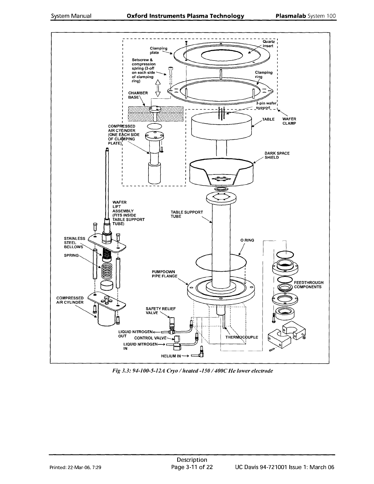
The helium-assisted
lower
electrode, shown in Fig 3.3,
is
fabricated
from
aluminium.
The
electrode
is
fitted
with
an
integral
dark
space shield.
The
lower
electrode
is
heated by an
embedded
12S0W
element
and cooled by
liquid
nitrogen
flowing
through
embedded
tUbing.
Wafer
lift
The
wafer
is
lifted
clear
of
the
table
(1Smm)
for
transferring
into
a load lock
or
transfer
chamber
by
the
wafer
lift
assembly. Compressed
air
flowing
into
the
air cylinder forces its
piston and
plunger
upwards. The
plunger
contacts
the
base
of
the
bellows
which
is
connected
to
a push rod. The 3-pin
wafer
support,
mounted
on
top
of
the
push rod, rises
lifting
the
wafer
clear
of
the
table. The push
rod
is
lowered
by
the
force
exerted
by
the
return
spring.
Wafer
clamp
The
wafer
clamp comprises a clamping
ring
attached
to
a
lifting
mechanism, and a clamping
plate. The clamping plate, attached
to
the
clamping
ring
via
three
pillars and screws,
comprises an
aluminium
annulus
with
a
quartz
circular insert.
The
wafer
clamp
is
raised and
lowered
by
two
air cylinders,
attached
to
the
outside
of
the
process chamber;
one
located
at
each side
of
the
wafer
clamp. The piston
of
each air cylinder
is
attached
to
a push rod,
which
passes
through
the
base
of
the
process chamber.
Within
the
process chamber, a circular
plate
mounted
on
the
top
of
the
push rod,
is
attached
to
the
wafer
clamp
by
three
MS
setscrews and compression springs.
Rotating
the
setscrews changes
the
compression
of
the
springs and consequently
the
clamping
force
exerted
on
the
wafer.
See
Section 6
for
the
clamping force
adjustment
procedure.
Note
that
clamping plates are available
with
inserts
for
various sized wafers. Before
loading
a
wafer
into
the
process chamber, ensure
that
the
correct clamping
plate
is
fitted.
See
Section 6
for
the
clamping
plate
changeover procedure.
Table
top
plate
In some systems,
the
table
top
plate
is
fixed
to
the
table
by
a
ring
of
cap-head bolts.
If
your
system has a
table
of
this type,
refer
to
the
following
text
and note.
The
bolt
heads are concealed
behind
screw covers,
which
require
a special
tool
(supplied
with
the
system)
for
removal. (Tool
part
number:
MD91 D21726.)
NOTES:
1)
When
re-fixing
the
table
top,
do
not
over-tighten
the
bolts
which
will
cause
the
table
top
to
bow.
Check
with
a
straight
edge
after
tightening:
if
the
table
top
is
not
flat,
release
the
bolt
tensions
until
it
is.
2)
The screw covers (MD91 D21723) are
aluminium.
When
removing
the
covers,
it
is
recommended
to
use a
little
iso-propyl alcohol (lPA)
to
prevent
the
thread
fromjamming.
Helium
backing
The purpose
of
helium
backing
is
to
set
the
temperature
of
the
wafer
close
to
that
of
the
temperature-controlled
table
by
heat
transfer. Helium
is
fed
from
a
number
of
small holes in
the
table
underneath
the
wafer
(which
is
clamped
to
the
table)
from
where
it
flows
radially
Printed: 22-Mar-06. 7:29
Description
Page 3-9
of
22
UC
Davis 94-721001
Issue
1: March 06
Plasma
lab
System
100
Oxford
Instruments
Plasma
Technology
System Manual
to
the
periphery
of
the
wafer.
Helium
is
the
preferred
gas, because
it
has a very
good
heat
transfer
ability. The use
of
other
gases
is
possible,
preferably
inert
gases.
The supply
of
helium
is
fed
by
a pressure
control
device,
which
receives an analogue
setpoint
from
the
machine's
control
system. The pressure
control
device adjusts
the
gas
flow
through
itself
to
control
the
pressure
at
its
output
side. The pressure
is
controlled
within
the
range 0
to
50 Torr. A pressure
of
greater
than
20
Torr
could damage very
thin
substrates.
If
the
wafer
is
clamped
down
successfully
the
chamber pressure
will
show
a
slight
rise
of
a
few
miliiTorr
when
the
helium
is
producing
a pressure
of
10
Torr
on
the
wafer.
If
there
is
a massive pressure rise and
the
Turbo
Controller
display shows a
high
load,
then
the
wafer
is
insufficiently
clamped
and
in
order
to
achieve
the
set pressure
the
controller
is
using
an excessive gas
flow.
The
helium
pressure
is
released
into
the
process chamber
at
the
end
of
a process (using a
normally-open
valve). This prevents
the
wafer
moving
when
it
is
undamped.
Tip:
Finish
a
process
with
a
ten-second
pumping
step
without
helium.
This
will
reduce
wafer
mishandling.
A
flow
meter
in
the
helium
supply also reads
the
gas
flow
necessary
to
maintain
the
pressure.
A typical process
uses
5 - 20
sccm
to
maintain
10 -15
Torr
behind
the
wafer.
Tip:
Some
wafers
mate
very
well
with
the
electrode
top
surface
and
use
less
than
2
sccm
to
maintain
10
Torr. This
can
give
a
control
problem,
with
the
helium
feeding
in
pulses.
Roughening
the
aluminium
electrode
with
an
abrasive
pad
can
increase
the
helium
flow
by
a
few
sccm
and
allow
proper
control.
Do
not
turn
on
the
helium
unless
the
wafer
is
clamped.
UC
Davis 94-721001
Issue
1:
March 06
Description
Page 3-10
of
22
Printed: 22-Mar-06, 7:29
System
Manual
Oxford
Instruments
Plasma
Technology
Plasma
lab
System
100
COMPR SSED
AIR
CYliNDER
(ONE
EAcH
SIDE
OFCL~PING
PLATE)
~
:::::::::=';;;;;;;;;;;;;;;;;;;;;:;::=="3-pin
wafer
I
~---Hrt-:.".....~_
- - _S!!0lQ!t -
~
TABLE WAFER
CLAMP
DARK SPACE
6~zr'"""
WAFER
LIFT
ASSEMBLY
(FITS INSIDE
TABLE SUPPORT
TUBE)
TABLE SUPPORT
TUBE
o RING
PUMPDOWN
PIPE FLANGE
SAFETY RELIEF
VALVE
Fig 3.3: 94-100-5-12A Cryo / heated-150/ 400C
He
lower electrode
Printed: 22-Mar-06. 7:29
Description
Page3-11of22
UC
Davis 94-721001
Issue
1: March 06