Oxford-100-Manual.pdf - 第246页
Plasma lab ICP 180 Oxford Instruments Plasma Technology WARNING Equipment Manual THE DIELECTRIC TUBE COULD FAIL CATASTROPHICALLY BY IMPLOSION WHEN UNDER VACUUM. IF IT IS NECESSARY TO OPEN THE RF ENCLOSURE FOR ANY REASON,…
Equipment
Manual
Oxford
Instruments
Plasma
Technology
Plasma
lab
fCP
180
3. Description
3.1
Function
The
Plasma
lab
ICP180
is
an Inductively Coupled Plasma
(ICP)
source suitable
for
the
Plasma
lab
System
100
or
equivalent
vacuum
equipment.
Its
function
is
to
create a
highly
ionized
low
pressure
plasma above a substrate,
without
the
need
to
couple
RF
power
to
the
plasma capacitively
through
the
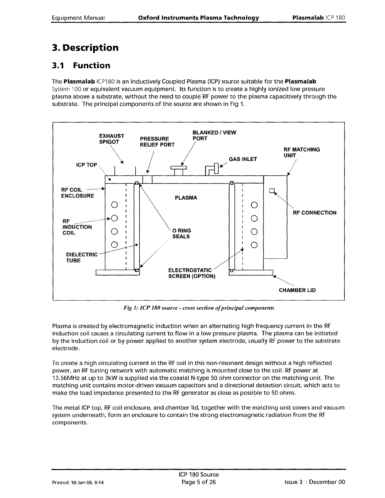
substrate. The principal components
of
the
source are
shown
in Fig
1.
RF MATCHING
UNIT
/
GAS INLET
~
BLANKED I VIEW
PORT
/
PRESSURE
RELIEF PORT
EXHAUST
SPIGOT
\
ICPTOP
RFCOIL
---
ENCLOSURE
PLASMA
0
0
RF
CONNECTION
RF
----_.--
,...0
0
-----
INDUCTION
0
o RING
0
COIL
SEALS
0
0
DIELECTRIC
TUBE
ELECTROSTATIC
SCREEN (OPTION)
CHAMBER LID
Fig 1: ICP 180 source - cross section ojprincipal components
Plasma
is
created by
electromagnetic
induction
when
an
alternating
high
frequency
current
in
the
RF
induction
coil causes a circulating
current
to
flow
in a
low
pressure plasma. The plasma can be
initiated
by
the
induction
coil
or
by
power
applied
to
another
system electrode, usually
RF
power
to
the
substrate
electrode.
To create a
high
circulating
current
in
the
RF
coil
in
this
non-resonant
design
without
a
high
reflected
power, an
RF
tuning
network
with
automatic
matching
is
mounted
close
to
the
coil.
RF
power
at
13.56MHz
at
up
to
3kW
is
supplied via
the
coaxial N-type 50
ohm
connector on
the
matching
unit.
The
matching
unit
contains
motor-driven
vacuum capacitors and a
directional
detection
circuit,
which
acts
to
make
the
load impedance presented
to
the
RF
generator
as
close
as
possible
to
50 ohms.
The
metal
ICP
top,
RF
coil enclosure, and chamber lid,
together
with
the
matching
unit
covers and vacuum
system
underneath,
form
an enclosure
to
contain
the
strong
electromagnetic
radiation
from
the
RF
components.
Printed: 18-Jan-06. 8:44
ICP
180 Source
Page 5
of
26
Issue
3 : December 00

Plasma
lab
ICP
180
Oxford
Instruments
Plasma
Technology
WARNING
Equipment
Manual
THE
DIELECTRIC
TUBE
COULD FAIL CATASTROPHICALLY BY IMPLOSION WHEN
UNDER
VACUUM.
IF
IT IS NECESSARY
TO
OPEN
THE
RF
ENCLOSURE
FOR
ANY
REASON, VENT
THE
CHAMBER,
OR
WEAR APPROPRIATE PERSONAL PROTECTION.
WARNING
DO
NOT OPERATE
THE
SOURCE WITHOUT
THE
COVERS PROPERLY ATTACHED.
PARTS
OF
THE
CIRCUIT OPERATE AT LETHAL VOLTAGES. RADIATION BURNS
MAY
OCCUR
TO
NEARBY PERSONNEL.
CAUTION
Nearby
electrical
equipment
may
experience
RF
interference
if
the
source
is
operated
without
all
covers
and
lids
forming
the
RF
enclosure
properly
secured.
Other
components
of
the
ICP180 include:
• A gas
inlet
connection,
1,4
inch
VCR
female
nut,
feeding
gas
to
distribution
holes in
the
ICP
top
lid.
• A
KF25
port.
intended
for
laser
interferometry.
• A 100mm
diameter
extraction
collar.
WARNING
IF
A QUARTZ ICP
TUBE
IS
FITTED, ULTRA-VIOLET LIGHT FROM
THE
PLASMA CAN
FORM OZONE
IN
THE
AIR INSIDE
THE
RF
ENCLOSURE. EXTRACTION SHOULD
BE
FITTED
TO
THIS
PORT;
EXTRACTION SHOULD
BE
FITTED
IF
THE
GASES USED
POSE
A
HAZARD
TO
PERSONNEL SHOULD
THE
ICP
TUBE
BREAK.
•
An
electrostatic screen. This minimises capacitive
coupling
between
the
RF
induction
coil and
the
plasma,
which
in
turn
reduces
ion
bombardment
of
the
tube
wall.
It
also eliminates cross-
coupling
between
the
ICP
RF
supply and any
other
RF
generator
on
the
same chamber,
making
phase-locking unnecessary. The electrostatic screen can be
omitted
if
the
ICP
180
is
the
only
plasma source
on
the
chamber.
• A pressure
relief
port. Should
the
system become pressurised, this
will
automatically
open
to
prevent
dangerous pressurisation
of
the
ICP
tube.
Issue
4:
January 06
ICP
180Source
Page 6
of
26
Printed: 18-Jan-06. 8:44
Equipment
Manual
Oxford
Instruments
Plasma
Technology
Plasma
lab
ICP
180
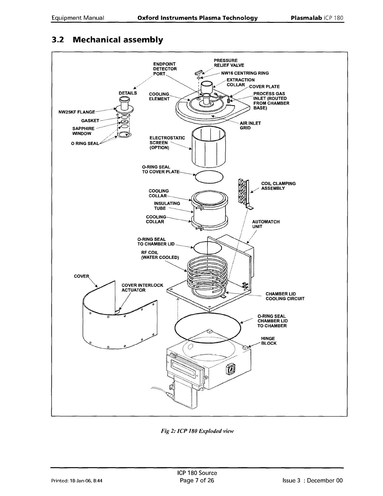
3.2
Mechanical
assembly
CHAMBER LID
COOLING CIRCUIT
HINGE
BLOCK
O-RING SEAL
CHAMBER LID
TO CHAMBER
AUTOMATCH
UNIT
1/
.,:
,
,
,
~
COIL CLAMPING
/ ASSEMBLY
,t;'
,
PRESSURE
REUEFVALVE
~
:k//~_-
NW16 CENTRING RING
----
/ EXTRACTION
:./
COLLAR COVER PLATE
I
PROCESS GAS
------INLET
(ROUTED
FROM CHAMBER
BASE)
ELECTROSTATIC
SCREEN
~
(OPTION)
~--
..
COOLlNG~
ELEMENT
---
o
O-RING SEAL
TO COVER
PLAT~
COOLING
COLLAR
INSULATING
TUBE
.----._~.~ilt:=::::::~
COOLING
COLLAR
o
O-RING SEAL
TO CHAMBER LID
o
o
ENDPOINT
DETECTOR
PORT
//
i/6./////
DETAILS
NW25KF
FLANGE.-----~
'i'J>C::'
....
GASKET
--------1
=--:
....----..-
..
~I
SAPPHIRE--
..
i.e:>:
WINDOW//O>
///c:Y
o RING
SEAL"""""·-
Fig 2:
ICP
180 Exploded view
Printed: 18-Jan-06, 8:44
ICP
180 Source
Page 7
of
26
Issue
3 : December 00