Oxford-100-Manual.pdf - 第98页
PlasmalabSystem 100 Oxford Instruments Plasma Technology System Manual 5.7.3 Rotary/dry pump N z purge flow rate adjustment CAUTION If the rotary/dry pump's N z purge flow rate is inadequate, damage to the pump coul…
System
Manual
Oxford
Instruments
Plasma
Technology
PlasmalabSystem
100
5.7.2
Adjusting
the
nitrogen
regulator
outlet
pressure
NOTE:
Refer
to
Section 2
for
a description
of
the
Nitrogen
vent
distribution
circuit.
The
regulator
outlet
pressure should
not
usually
require
adjustment
from
its
factory
setting.
However,
if
adjustment
is
necessary, proceed
as
follows.
WARNING
THIS PROCEDURE INVOLVES WORKING ON THE SYSTEM WITH COVERS REMOVED
AND
WITH THE ELECTRICAL POWER ON. THEREFORE IT MUST ONLY
BE
CARRIED OUT
BY TRAINED
AND
COMPETENT PERSONNEL
WHO
ARE AWARE
OF
THE RISKS
INVOLVED.
1)
Remove system panels
as
necessary
to
gain
access
to
the
regulator.
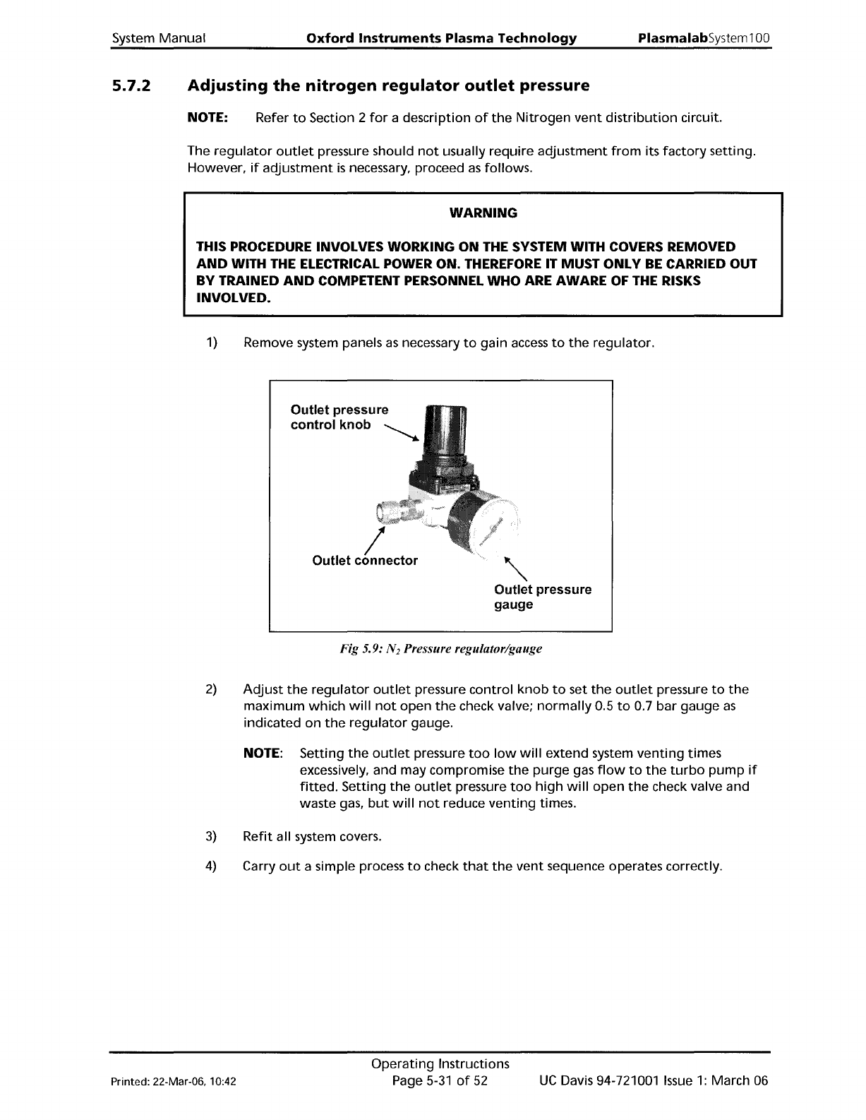
Outlet
pressure
control
knob
~
/
Outlet
connector
'"
Outlet
pressure
gauge
Fig 5.9: N
2
Pressure regulator/gauge
2)
Adjust
the
regulator
outlet
pressure
control
knob
to
set
the
outlet
pressure
to
the
maximum
which
will
not
open
the
check valve;
normally
0.5
to
0.7
bar
gauge
as
indicated
on
the
regulator
gauge.
NOTE: Setting
the
outlet
pressure
too
low
will
extend
system
venting
times
excessively, and may compromise
the
purge
gas
flow
to
the
turbo
pump
if
fitted.
Setting
the
outlet
pressure
too
high
will
open
the
check valve and
waste gas,
but
will
not
reduce
venting
times.
3)
Refit
all system covers.
4)
Carry
out
a simple process
to
check
that
the
vent
sequence operates correctly.
Printed: 22-Mar-06, 10:42
Operating
Instructions
Page
5-31
of
52
UC
Davis 94-721001
Issue
1:
March 06
PlasmalabSystem100
Oxford
Instruments
Plasma Technology
System Manual
5.7.3
Rotary/dry
pump
N
z
purge
flow
rate
adjustment
CAUTION
If
the
rotary/dry
pump's
N
z
purge
flow
rate
is
inadequate,
damage
to
the
pump
could occur.
Ensure
that
the
flow
rate
is
set
to
the
value
recommended
by
the
pump
manufacturer.
The
rotary/dry
pump's
N
z
purge
flow
rate
is
set
at
the
factory
before
system
shipment
and
should
not
need adjustment. However,
the
pump
purge
rate
will
need
to
be
confirmed
on
installation
and
at
any
time
the
purge
gas supply pressure changes significantly.
If
adjustment
is
necessary,
refer
to
Appendix
R in this manual.
UC
Davis 94-721001
Issue
1:
March 06
Operating
Instructions
Page 5-32
of
52
Printed: 22-Mar-06. 10:42
System
Manual
Oxford
Instruments
Plasma
Technology
PlasmalabSystem100
5.8
5.8.1
PC
2000
screens
Pump
control
page
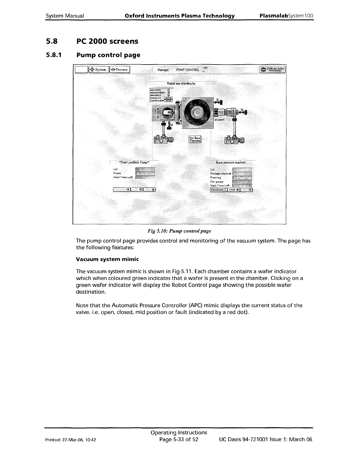
Fig 5.10: Pump controlpage
The
pump
control
page provides
control
and
monitoring
of
the
vacuum system. The page
has
the
following
features:
Vacuum
system
mimic
The vacuum system
mimic
is
shown in Fig 5.11.
Each
chamber contains a
wafer
indicator
which
when
coloured green indicates
that
a
wafer
is
present in
the
chamber. Clicking on a
green
wafer
indicator
will
display
the
Robot
Control
page
showing
the
possible
wafer
destination.
Note
that
the
Automatic
Pressure
Controller
(APC)
mimic displays
the
current
status
of
the
valve, i.e. open, closed,
mid
position
or
fault
(indicated
by
a red dot).
Printed: 22-Mar-06, 10:42
Operating
Instructions
Page 5-33
of
52
UC
Davis 94-721001
Issue
1:
March 06