IPC-T-50F_.pdf.pdf - 第15页
Bump (Die) 74.0159 A raised metal feature on a die land or tape carrier tape that facilitates inner-lead bonding. Bumped Die 74.0160 A semiconductor die with raised metal features that facili- tate inner-lead bonding. Bu…
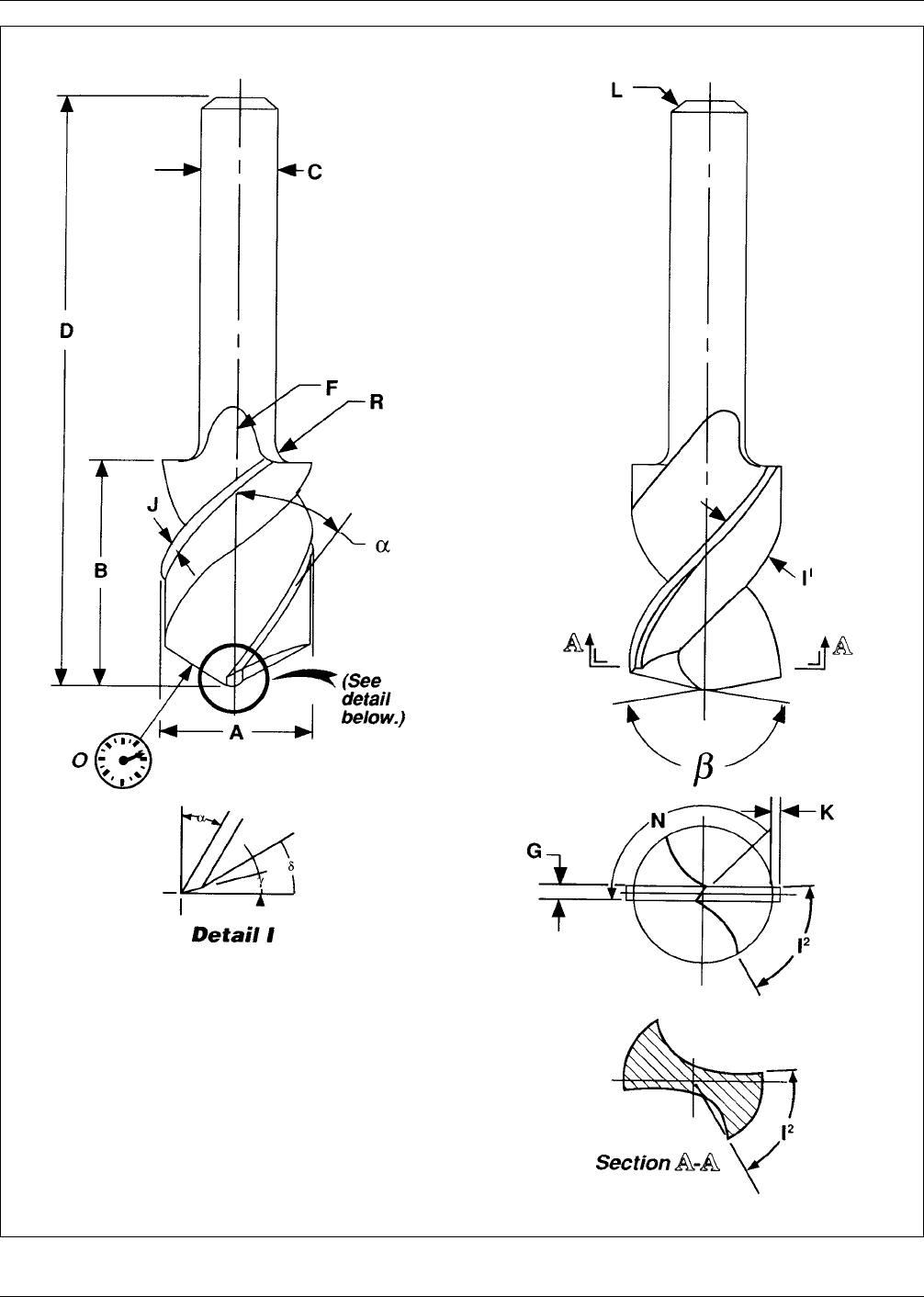
Figure B–4 Drill Features
IPC-T-50F June 1996
10

Bump (Die) 74.0159
A raised metal feature on a die land or tape carrier tape that
facilitates inner-lead bonding.
Bumped Die 74.0160
A semiconductor die with raised metal features that facili-
tate inner-lead bonding.
Bumped Tape 74.0161
Carrier tape with raised metal features that facilitate inner-
lead bonding.
Bumped Wafer 74.0162
A semiconductor wafer with raised metal feature on its die
lands that facilitate inner-lead bonding.
Buried Via 22.0163
A via that does not extend to the surface of a printed board.
(See Figure B-3.)
Burn-In 95.0164
The process of electrically stressing a device at an elevated
temperature, for a sufficient amount of time to cause the
failure of marginal devices (Infant Mortality).
Burn-In, Dynamic 95.0165
Burn-in at high temperatures that simulates the effects of
actual or simulated operating conditions.
Burn-In, Static 95.0166
Burn-in at high temperatures with unvarying voltage, either
forward or reverse bias.
Burn-Off 74.0167
see ‘‘Flame-Off.’’
Bus 21.0168
One or more conductors used for transmitting data signals
or power.
Bus Bar 37.0169
A conduit, such as a component or conductor on a printed
board, that is used for distributing electrical energy. (See
also ‘‘Plating Bar.’’)
Butt Leads 36.1732
A SMT lead form. Leads extending horizontally from about
the center of a component body, formed down at a 90
degree angle and ending immediately below the component
body without additional bends.
Butter Coat 41.0170
An increased amount of resin on the outer surface of a base
material.
C
C-Staged Resin 41.0171
A resin in its final state of cure. (See also ‘‘B-Staged
Resin.’’)
Camber 92.0172
The planar deflection of a flat cable or flexible laminate
from a straight line.
Cap Lamination 55.0176
A process for making multilayer printed boards with sur-
face layers of metal-clad laminate bonded in a single
operation. (See also ‘‘Foil Lamination.’’)
Capability Detail Specification (CapDS) 26.1780
A document that establishes the specific requirements,
noted in a detailed specification, in order to establish the
level of capability that a manufacturer posesses when he
has demonstrated that he has met those requirements.
Capability Index (Cp) 91.0306
see ‘‘Capability Performance Index.’’
Capability Performance Index (Cp) 79.1806
The ratio of the measured performance of a process com-
pared to specified limits.
Capability Performance, Lower (Cpkl) 91.1367
A measure of the relationship between the performance of
a process and the lower specification limit. (See also
‘‘Capability Performance, Upper.’’)
Capability Performance, Upper (Cpku) 91.1344
A measure of the relationship between the performance of
a process and the upper specification limit. (See also
‘‘Capability Performance, Lower.’’)
Capability Test Board (CTB) 94.1784
A printed board specifically designed to act as a capability
qualifying component (CQC), or to be used by manufac-
turer to evaluate process variation, process control, or con-
tinuous improvement procedures.
IPC-I-001036
Figure B–5 Bow
BOW
June 1996 IPC-T-50F
11
Capability Test Segment (CTS) 94.1785
A segment or portion of a capability test board (CTB),
containing a set or group of individual test patterns (ITP),
intended to be used to demonstrate a specific level of
printed board complexity or manufacturing capability.
Capacitance 21.1794
A measure of the ability of two adjacent conductors sepa-
rated by an insulator to hold a charge when a voltage is
impressed between them.
Capacitance Density 21.0173
The amount of capacitance available per unit area.
Capacitive Coupling 21.0174
The electrical interaction between two conductors that is
caused by the capacitance between them.
Capillary 74.0175
A hollow bonding tool used to guide wire to the bonding
site and to be used to apply pressure during the bonding
cycle. (See also ‘‘Wedge Tool’’)
Card 60.0177
see ‘‘Printed Board.’’
Card-Edge Connector 22.0178
see ‘‘Edge-Board Connector.’’
Card-Insertion Connector 22.0179
see ‘‘Edge-Board Connector.’’
Carrier (Foil) 45.0180
A temporary support medium that facilitates the handling
of thin and soft-metal foils.
Carrier Tape 36.1345
The carrier for conductors used in tape-automated bonding.
(See also ‘‘Multilayer Carrier Tape,’’ ‘‘Single-Layer Carrier
Tape,’’ ‘‘Two-Layer Carrier Tape’’ and ‘‘Three-Layer Car-
rier Tape.’’)
Carry-Out 51.0181
The curved back portion of the flute of a drill.
Castellation 33.0182
A recessed metalized feature on the edge of a leadless chip
carrier that is used to interconnect conducting surface or
planes within or on the chip carrier.
Catalyst (Resin) 40.0183
A chemical that is used to initiate the reaction or increase
the speed of the reaction between a resin and a curing
agent.
Catalyzing 53.0184
see ‘‘Activating.’’
Cathodic Cleaning 57.0185
Electrolytic cleaning in which the work is the cathode.
Cation Exchange 59.0186
see ‘‘Ion Exchange’’
Cationic Reagent 59.0187
Surface-active substances that have the active constituent
in the positive ion.
Cause-and-Effect Diagram 94.0188
A problem solving tool that uses a graphic description of
various process elements in order to analyze potential
sources of process variation.
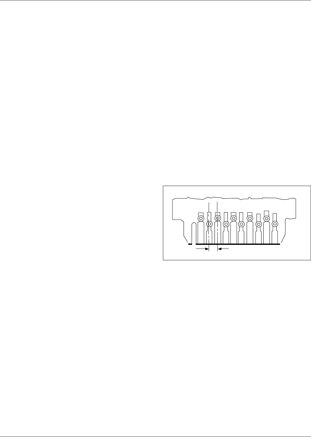
Center-to-Center Spacing 22.1346
The nominal distance between the centers of adjacent fea-
tures on any single layer of a printed board. (See Figure
C-1.)(See also ‘‘Pitch.’’)
Centering Force 73.1733
The force required by the pick-up tooling to center a sur-
face mounting device in its proper location on a substrate.
Centerwire Break 74.0189
A failure mode in a wire pull test whereby the wire frac-
tures at approximately its midspan.
Central Line 91.0190
The line on a control chart that depicts the average or
median value of the items being plotted.
Certification 17.0191
The verification that specified training or testing has been
performed and that required proficiency or parameter val-
ues have been atained.
Chain Dimensioning 26.0192
The maximum variation between two features that is equal
to the sum of the tolerances on the intermediate distances.
IPC-I-001035
Figure C–1 Center-to-center spacing (pitch)
Pitch
IPC-T-50F June 1996
12