YG300_Ope_E.pdf - 第105页
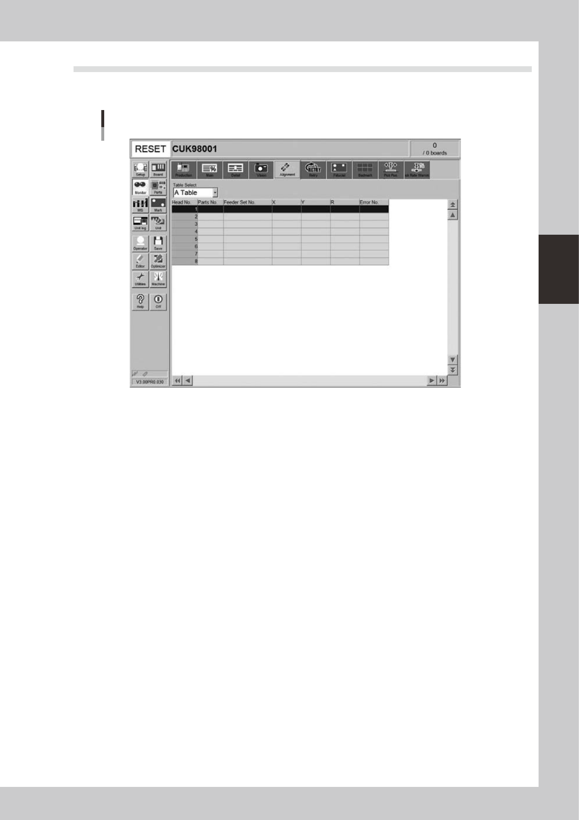
3-19 3 Starting and ending pr oduction 4 . 5 A l i g n m e n t T h e [ A l i g n m e n t ] t a b s c r e e n s h o w s t h e o f f s e t a m o u n t o f e a c h h e a d c a l c u l a t e d f r o m t h e r e c o g n i t i…

3-18
3
Starting and ending production
• Mark monitor mode
This specifies the monitor display mode during mark recognition. The recognition results and binary image will appear
on the image according to the selected item. This monitor mode can be changed during operation.
"None"
Displays an image taken by the camera. The recognition result values are not displayed.
"Result"
Displays the center position coordinates (pixels) of the detected mark.
"Binary Image"
Displays the image taken by the camera as a binary image.
"Grey Image"
Displays an image that was processed after being captured by the camera. The recognition result values are not
displayed.
"Search Result"
Draws a line to indicate the boundary between the recognized mark and the background.
"Datum Circle"
Draws a mark of the specified diameter from the center of the detected mark. (Possible only in specific recognition
modes.)
"Tangent Circle"
Draws an inscribed circle and circumscribed circle from the center of the detected mark. (Possible only in specific
recognition modes.)
"Error Image"
Displays the error image. (Possible only in specific recognition modes.)
"Individual data"
Displays the individual data when multiple objects are detected. (Possible only in specific recognition modes.)
• Img Check (Image Check)
Pressing this button allows you to check and save an image that was recognized immediately before the machine stopped
during automatic operation. The camera and head can be specified when checking and saving an image.
3-19
3
Starting and ending production
4.5 Alignment
The [Alignment] tab screen shows the offset amount of each head calculated from the recognition results
obtained during automatic operation, as well as error numbers.
Monitor: Alignment
24313-M3-00
• Head No.
Shows the head No. used in the machine. The recognition results of the head No. used in the sequence that starts from
the current pickup are displayed. Note that the display is made after the camera image recognition has completed.
• Parts No.
Shows the number of the component picked up by the head and recognized with the camera.
• Feeder Set No.
Shows the feeder set number of the component picked up by the head and recognized with the camera.
• X, Y, R
Displays the offset amount of each head calculated from the recognition results obtained during automatic operation.
This offset is the positional deviation from the center of the nozzle.
• Error No.
Shows an error number when the head fails to recognize a component.
3-20
3
Starting and ending production
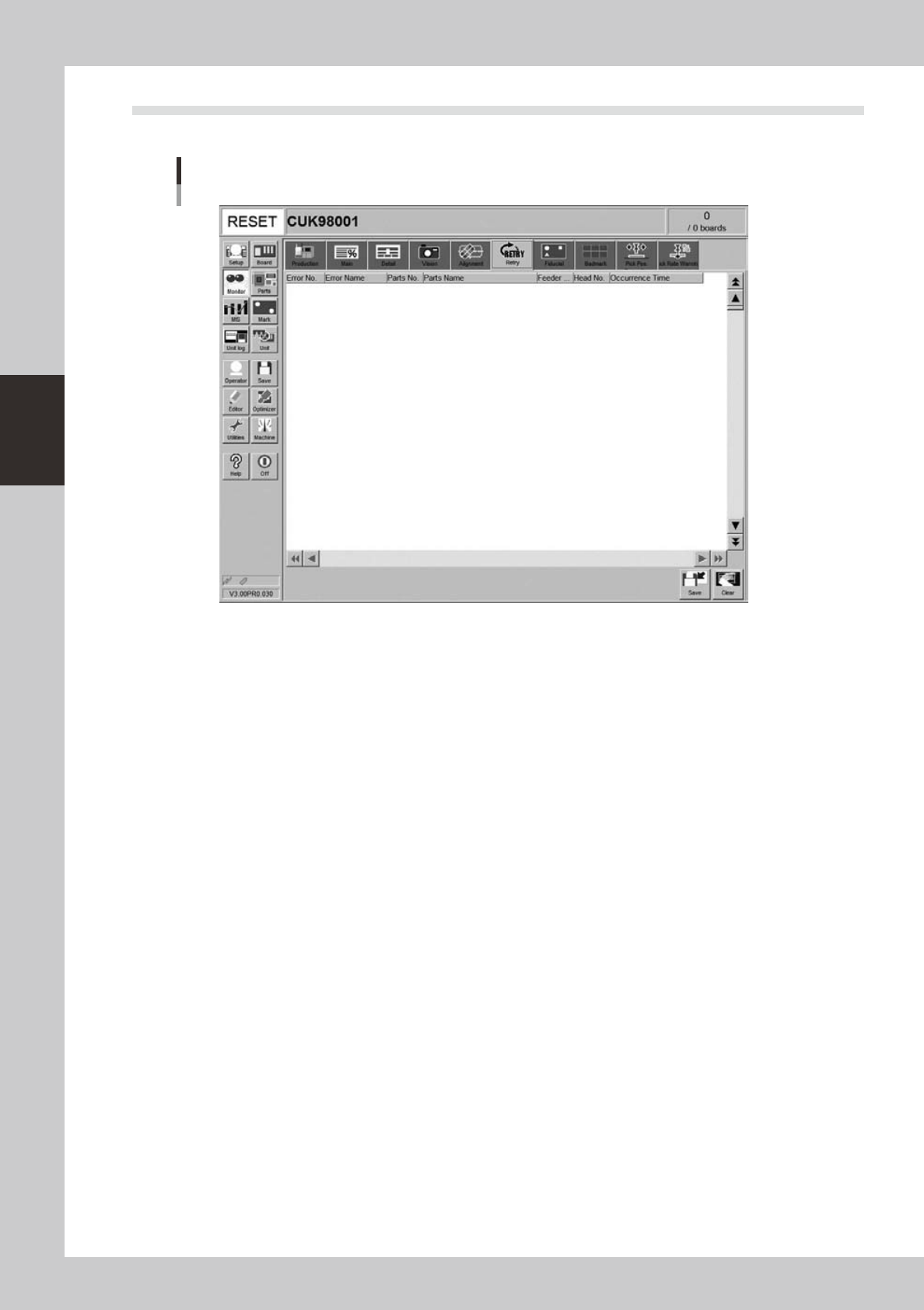
4.6 Retry
The [Retry] tab screen displays the history or the past 100 errors.
Monitor: Retry
24314-M3-00