YG300_Ope_E.pdf - 第64页
2-11 2 Basic operation 2 . 2 S e t u p s c r e e n T h i s s e c t i o n d e s c r i b e s t h e o p e r a t i o n b u t t o n s d i s p l a y e d o n t h e S e t u p s c r e e n . Setup screen 1 2 3 4 5 6 7 8 9 10 11 12…
2-10
2
Basic operation
About error screen
Error screen
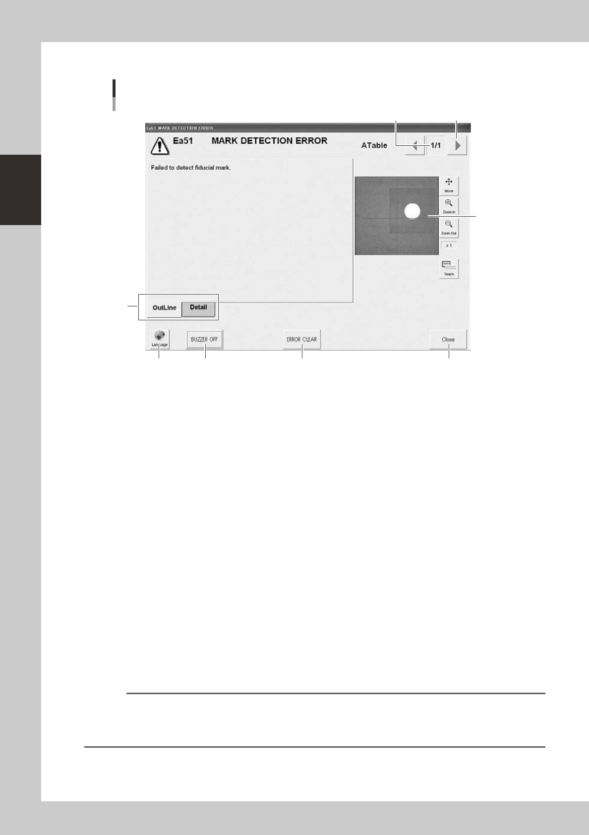
Mark detection error
1
2
3
6 74 5
[Error Switching] button
24202-M3-00
1. Error count display
Shows the currently displayed error and the total number of errors. If two or more errors occurred, use the [Error
Switching] buttons (right/left arrow buttons) to switch to other error screens.
2. Message switching tab
Outline:
Displays a message for the operator.
Detail:
Displays a message for the administrator/supervisor or service personnel. This tab does not appear unless a message is
available.
3. Recognition image display (component pickup error and mark recognition error screens)
If an error has occurred in image processing during component pickup or mark recognition, the error image is displayed
here.
4. [BUZZER OFF]
Turns off the buzzer.
5. [ERROR CLEAR]
Clears the error that has occurred.
6. [Language] button
Switches the language of the message displayed on the error screen.
7. [Close] button
Closes the error screen without clearing the error.
Reference
After closing the error screen by pressing the [Close] button, you can check the locations where errors have occurred
by opening the [Monitor] - [Production] tab. Pressing the [Error Detail] button on the [Production] tab screen redisplays
the error message. For more details on the [Production] tab screen, refer to section 4, "Starting and ending
production", later in this chapter.
2-11
2
Basic operation
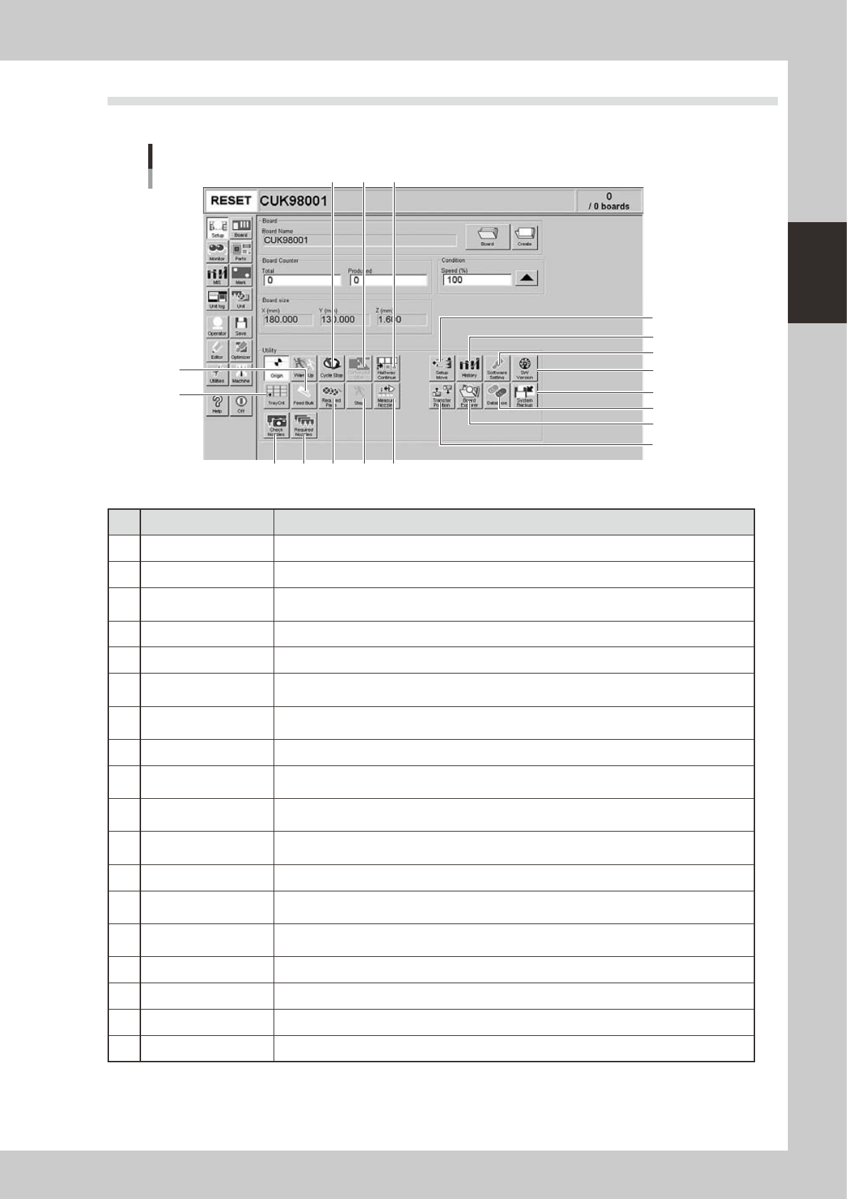
2.2 Setup screen
This section describes the operation buttons displayed on the Setup screen.
Setup screen
1
2
3
4
5
6
7
8
9
10 11
12
131415
16
17
18
24203-M3-00
Button name Function
1 Setup Move Moves the head to the front left position, and the stage to the component placement position.
2 Transfer position Aligns all stages in a line so that each conveyor is ready to transfer boards.
3 History
Saves production history data, and saves or clear any desired items of "MIS" and "Unit log"
records. Also use this button when removing a storage medium from the machine.
4
Software Setting
Sets machine screen display items, adds or deletes operators, and sets passwords.
5 Version Shows version information on application software and system.
6 System Backup
Makes a backup of machine coordinates, accuracy information, option device information and
standard coordinates necessary for machine operation or restores the data using the backup.
7 Database
Makes a backup of parts and mark database necessary for board production or restores the data
using the backup. Also sets the database locations.
8 Board Explorer Moves, backs up, restores or copies board data.
9 Cycle Stop
Stops machine operation just after mounting components on the current board, for example, to
check the mounted results or to prevent the board from flowing to the downstream machine.
10 Convey-out Stop
Stops machine operation after mounting components on all boards on the conveyor and
transferring them to the downstream machine.
11 Halfway Continue
After stopping the machine for some reason during component mounting and resetting the data,
pressing this button loads that data to resume component mounting from the next mount point.
12 Measure Nozzles Acquires the shape images of nozzle tips for chip components.
13 Step
Temporarily stops the machine at a specific position, for example, during initial component
mounting, test mounting, or trouble analysis.
14 Required Parts
Displays the component types and feeder positions that are set up for the production to be
started.
15 Required Nozzles Displays a list of nozzles to be used.
16 Check Nozzles Checks if nozzle tips for chip components are dirty or clogged by acquiring their images.
17 Tray Cnt Displays the number of tray components that have been used.
18 Feed Bulk Feeds bulk components to the pickup position of a bulk feeder.
2-12
2
Basic operation
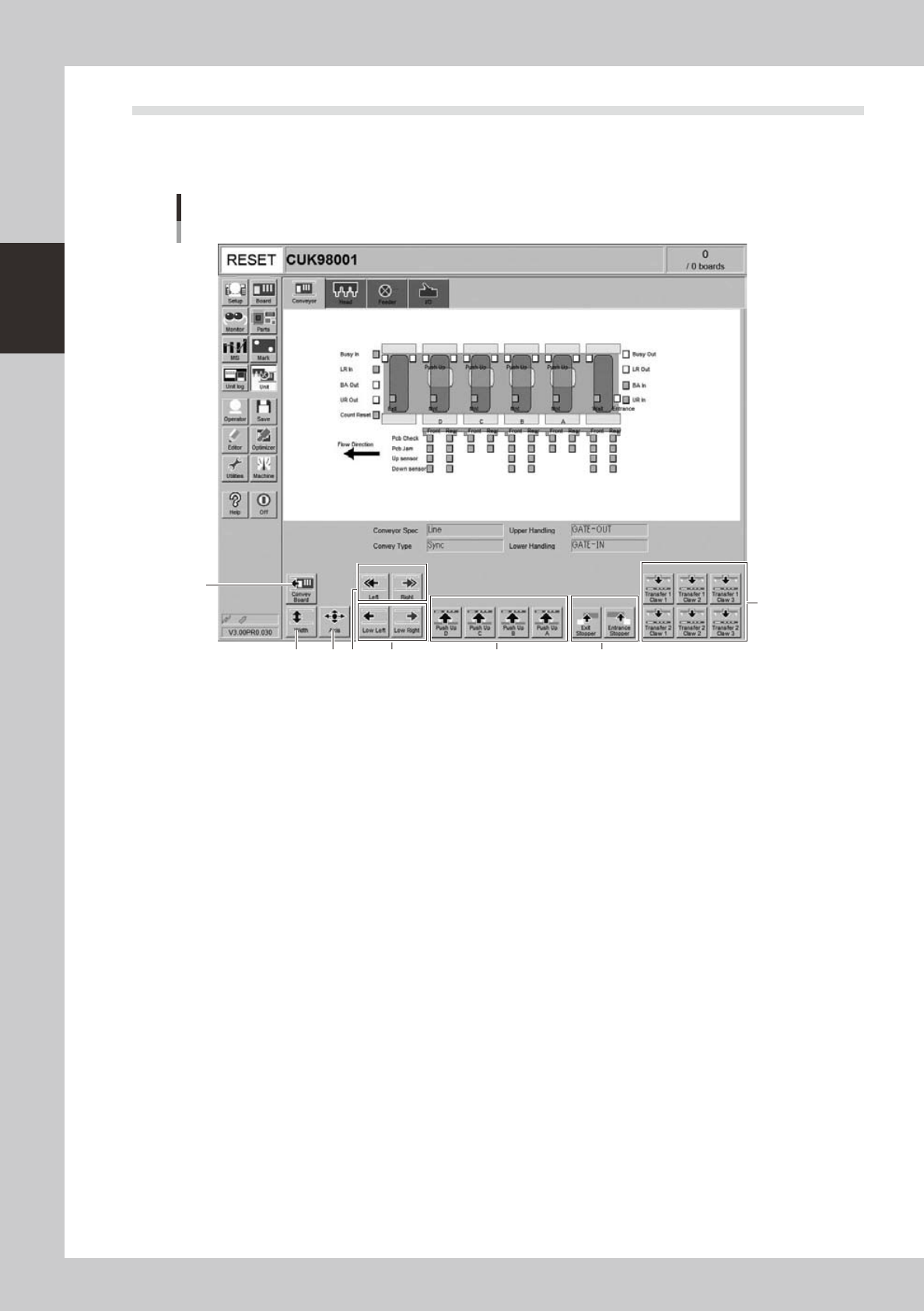
2.3 Unit screen
This section describes the manual operation buttons on the Unit screen.
n
Manual conveyor operation
3
1
2 4 6
8
7
Conveyor manual buttons
5
24204-M3-00