YG300_Ope_E.pdf - 第81页
2-28 2 Basic operation 3 . 5 P r e p a r i n g t h e c o m p o n e n t s u p p l y u n i t 3 . 5 . 1 T a p e f e e d e r 1 . C h e c k i n g t h e f e e d p i t c h a n d a c t i o n P r e s s t h e m a n u a l f e e d l…
2-27
2
Basic operation
5
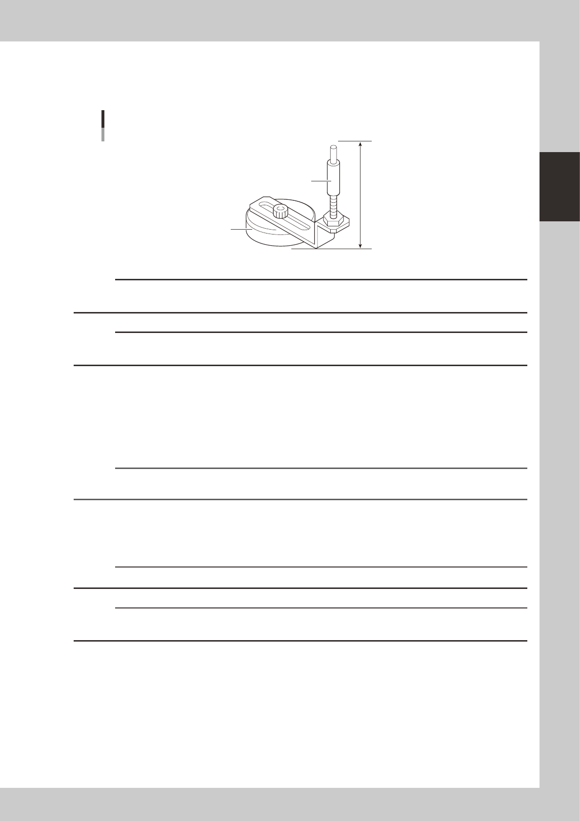
Place the push-up pins in the correct positions on the push-up plate.
Push-up pins are attached on the push-up plate by magnet. Considering the shape and size of the
board, place the push-up pins on the push-up plate so that they uniformly support the board, including
the edge of the board.
55mm
Support pin
Pushup pin
Magnet stand
23205-M3-00
c
CAUTION
The push-up pin height from the bottom of the magnet to the top of the pin shaft is set to 55mm. Do not change this
height.
c
CAUTION
Set the push-up pins in positions where they will not interfere with the conveyor rails and other parts when the push-up
plate is raised.
6
Raise the push-up plate.
Check safety and press the [Push Up A to D] buttons (for the target stage) on the Setup screen. The
push-up plate moves up to clamp the board.
7
Check that the board is uniformly clamped on the conveyor.
Lightly tap on the board and also check for warping of the board from the side. If the board is
supported evenly with no warping, the adjustment is okay.
Reference
It may be convenient to mark the positions of the push-up pins on the plate (with a label, magic marker, etc.) for each
board type.
8
Remove the board from the conveyor.
1. Press the [Push Up A to D] buttons (for the target stage) to lower the push-up plate.
2. Unlock the board flap and remove the board. Lock the board flap after removing the board.
c
CAUTION
Be sure to lock the board flap. If not locked, the sensor works to prohibit operation.
c
CAUTION
When the board flap is locked, the guide pins should fit in the board flap. Raise and lower the guide pins to make sure
that they securely fit in the board flap.
9
Make conveyor setup on the next transport stage.
Repeat steps 2 to 8 on all stages.
2-28
2
Basic operation
3.5 Preparing the component supply unit
3.5.1 Tape feeder
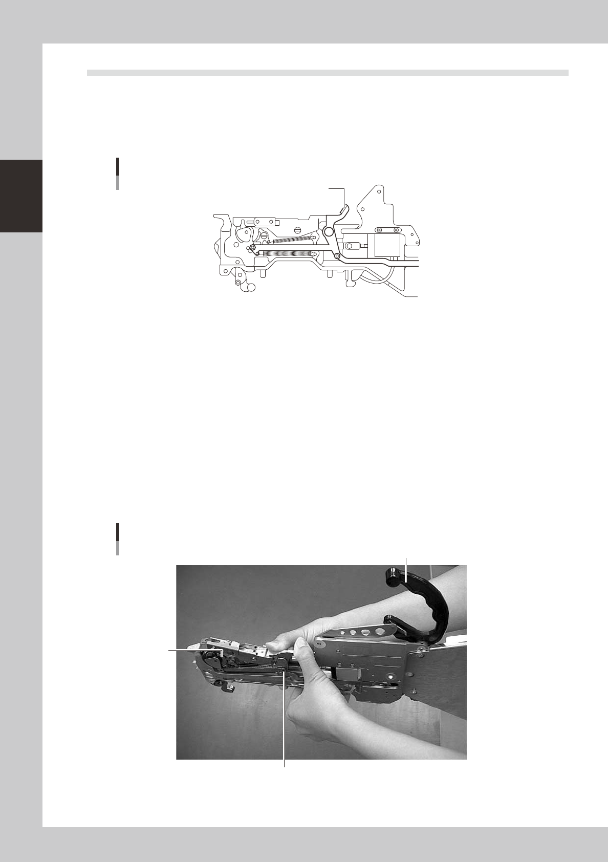
1. Checking the feed pitch and action
Press the manual feed lever to make sure that the tape is fed at a proper pitch.
Manual feed lever
Manual feed lever
23206-M0-00
2. Setting the tape
When fitting a new roll of tape to a tape feeder, set the tape with the procedure below. This section explains the
procedure using a CL type tape feeder as an example.
1
Peel off the top tape.
Tape consists of two layers: "carrier tape" that contains electronic components in the pockets and "top
tape" that covers the upper side of components on the carrier tape. Peel off the top tape to separate
these two layers.
2
Lift the clamping lever lock handle.
Lift the clamping lever lock handle to lift the tape guide.
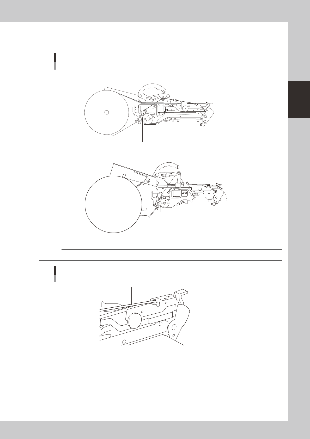
3
Lift the tape guide.
Lift the tape guide while pressing the lock lever.
After the tape guide is lifted, return the lock lever to the original position and hold the tape guide in the
raised position.
Tape guide
Lock lever
Tape guide
Clamping lever lock handle
23217-M0-00
2-29
2
Basic operation
4
Set the tape in the tape feeder.
Set the separated layers of the tape on the tape feeder through the tape paths shown in the picture
below.
CL type tape feeder
: Top tape
: Carrier tape
A to E
E
A
a
a to c
c
C
B
b
D
8mm tape feeder
12mm, 16mm tape feeder
A
a
C
B
b
c
E
D
Tape path example
23208-M0-00
n
NOTE
Pass the top tape through the notch in the tape guide and turn it back.
Turning the top tape
Top tape
Notch
23209-M0-00