YG300_Ope_E.pdf - 第111页
3-25 3 Starting and ending pr oduction 4 . 1 0 P i c k R a t e Wa r n i n g T h i s s c r e e n a p p e a r s w h e n t h e p i c k u p r a t e w a r n i n g f u n c t i o n i s u s e d . T h i s s c r e e n a l l o w s …

3-24
3
Starting and ending production
• Count
Displays the number of components that were picked and placed by the nozzle for which the pickup position offset
function is on (enabled).
• [All Reset] button
This button clears and resets pickup position offset data for all components shown on the monitor.
• [Current Reset] button
Clears and resets pickup position offset data for a component selected from among components shown on the monitor.
3-25
3
Starting and ending production
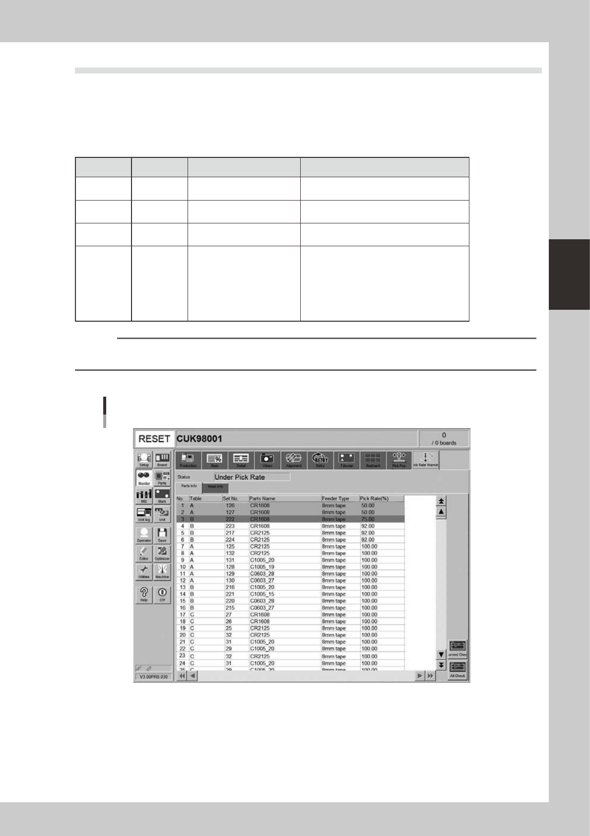
4.10 Pick Rate Warning
This screen appears when the pickup rate warning function is used. This screen allows checking for a drop in
the component pickup rate on each component or head. Clicking the tab to switch the display.
The pickup rate is reset in real-time after mounting a group of components. However, if a particular component
or head is not used then its row will not appear on the display. Pickup rates can be monitored by color during
operation.
n
Display color
Color of row Status Pickup Rate Description
White 100% to [caution (yellow)]%
Pickup rate is above [caution (yellow)]% and
below (or equal to) 100%.
Yellow Caution
[caution (yellow)]% to [warning
(red)]%
Pickup rate is above [warning (red)]% and
below (or equal to) [Caution (yellow)]%.
Red Warning [warning (red)]% to 0%
Pickup rate is above (or equal to) 0% and
below (or equal to) [warning (red)]%.
Pink
Watch-and-
wait mode
Optional
When the pickup rate is [warning (red)]%
or less, pressing the [Current Check] or [All
Check] button enables "watch-and-wait" mode
and the color of the "red" row(s) changes to
"pink".
Note that operation is not stopped in this mode
even if stop control setting is made.
n
NOTE
Numerical values (%) in brackets [ ] are machine data setting items, so an administrator right is required to change
them.
[Parts Info] tab
Monitor: Pick Rate Warning
Parts info
24318-M3-00
• No.
Displays the component No. (Parts screen data No.).
• Table
Displays the feeder table (feeder plate location) where the component feeder is installed.
• Set No.
Displays the feeder set position at which the component feeder is installed.
3-26
3
Starting and ending production
• Parts name
Displays the component name.
• Feeder Type
Displays the type of feeder.
• Pick Rate (%)
Displays the pickup rate for each component. Rate is calculated by the following formula.
1 – ([Error count] ÷ [Number of components used]) = Pickup rate
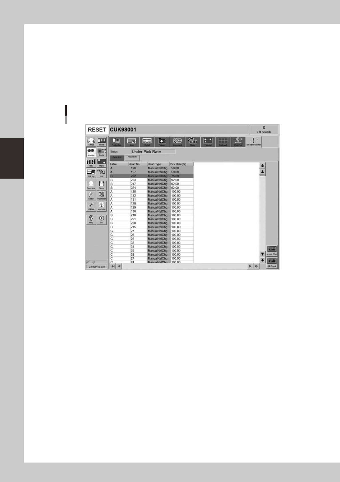
[Head Info] tab
Monitor: Pick Rate Warning
Head info
24319-M3-00
• Table
Displays the feeder table (feeder plate location).
• Head No.
Displays the head No. being used.
• Head Type
Displays the type of head being used.
• Pick Rate (%)
Displays the pickup rate for each head. Rate is calculated by the following formula.
1 – ([Error count] ÷ [Number of components used]) = Pickup rate
• [Current Check] button
Selecting a component (row) from among components with abnormal pickup rates (rows shown in "red") and clicking this
button sets "watch-and-wait" mode for that component.