YG300_Ope_E.pdf - 第33页
1-5 1 Part names and functions 2 . 2 O p e r a t i o n p a n e l b u t t o n s T h e o p e r a t i o n p a n e l b u t t o n s a r e p r o v i d e d o n t h e f r o n t a n d r e a r ( o p t i o n ) o f t h e m a c h i n…
1-4
1
Part names and functions
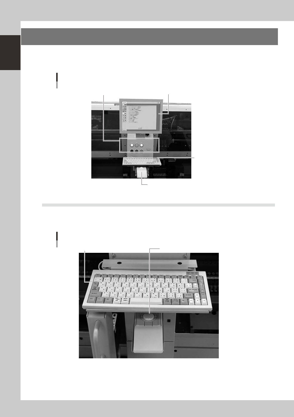
2. Operation panel and data input unit
Standard machines are equipped with an operation display, operation panel buttons, a keyboard and a
trackball on the front and rear of the machine, to operate the machine and make data settings. The functions
of these units are explained below.
Operation display (touch screen is optional)
Trackball
Keyboard
Operation panel button
Operation panel and data input unit
23102-M3-00
2.1 Keyboard and mouse
This machine is equipped with keyboards and trackballs as standard features to operate the machine or edit
data settings. To select a menu button or parameter item on the operation screen, place the cursor on it and
press the trackball button. (A keyboard and trackball are installed on the front and rear of the machine.)
Keyboard and trackball
Keyboard Trackball
23103-M3-00
1-5
1
Part names and functions
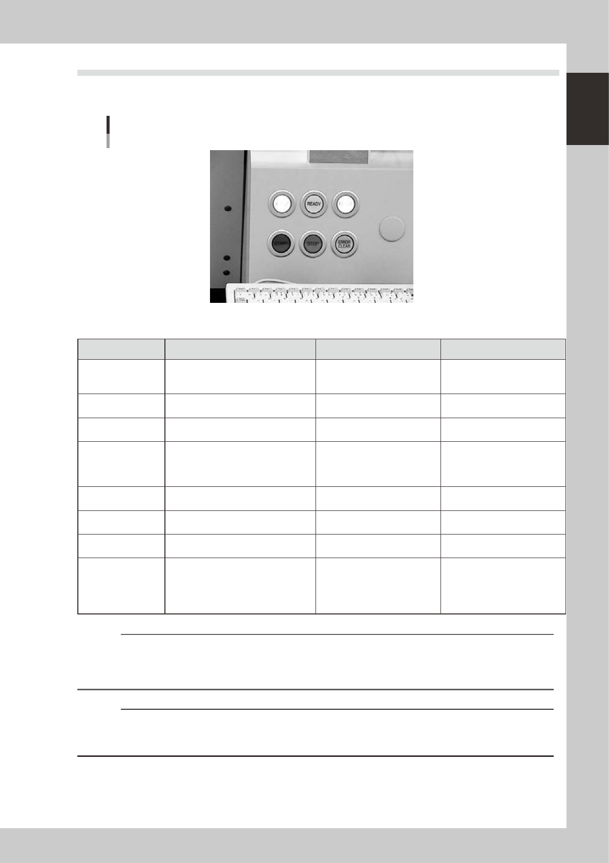
2.2 Operation panel buttons
The operation panel buttons are provided on the front and rear (option) of the machine to run major commands
frequently used to operate the machine. Each button is lit while turned on.
Operation panel buttons
23104-M3-00
n
Operation panel button functions
Button name Use the button to: OFF ON
ACTIVE
Enable other keys. (The front and rear
[ACTIVE] keys cannot be turned on
simultaneously.)
• After machine has started.
• The other table has access
rights to operate machine.
• This table has access rights to
operate machine.
READY
Release emergency stop and turn the
servo on.
• SERVO OFF
(Motor power OFF)
• SERVO ON
(Motor power ON)
RESET
Stop automatic operation and return to
standby for board production.
• Machine is in normal operation
or stopped.
• Machine has been reset.
START
Perform component placement
according to board data.
Resume board production when the rear
table is ready to recover.
• Machine is stopped. • Machine is in normal operation.
STOP
Interrupt automatic operation. (Press
START to resume operation.)
• Machine is in normal operation. • Error occurred.
ERROR CLEAR
Stop buzzer sound and clear error
screen.
• Machine is in normal operation. • Error occurred.
EMERGENCY STOP
Trigger emergency stop. Turn to the
right to release it.
RECOVER
Resume component placement on the
table that was stopped due to some
errors, after first clearing all errors.
This button is provided on each
component placement table (A to D).
• Machine is in normal operation.
• Component placement was
resumed after clearing error.
[Flashing]
• Pause or step operation
• Error occurred on the relevant
table.
n
NOTE
The [ACTIVE] button is provided on both front and rear (option) panels, but cannot be turned on simultaneously. This
means that the [READY], [START], [ERROR CLEAR] and [RESET] buttons are enabled only when the [ACTIVE] key on the
same panel is turned on. (The [STOP] button can be used when the [ACTIVE] button is either on or off.)
The keyboard is enabled only when the [ACTIVE] key on the front panel is on.
c
CAUTION
Even if the [RECOVER] button is pressed, the machine cannot resume component placement unless an error that
occurred on the relevant table is cleared. Clear the error and then press the [RECOVER] button again to resume
component placement.
1-6
1
Part names and functions
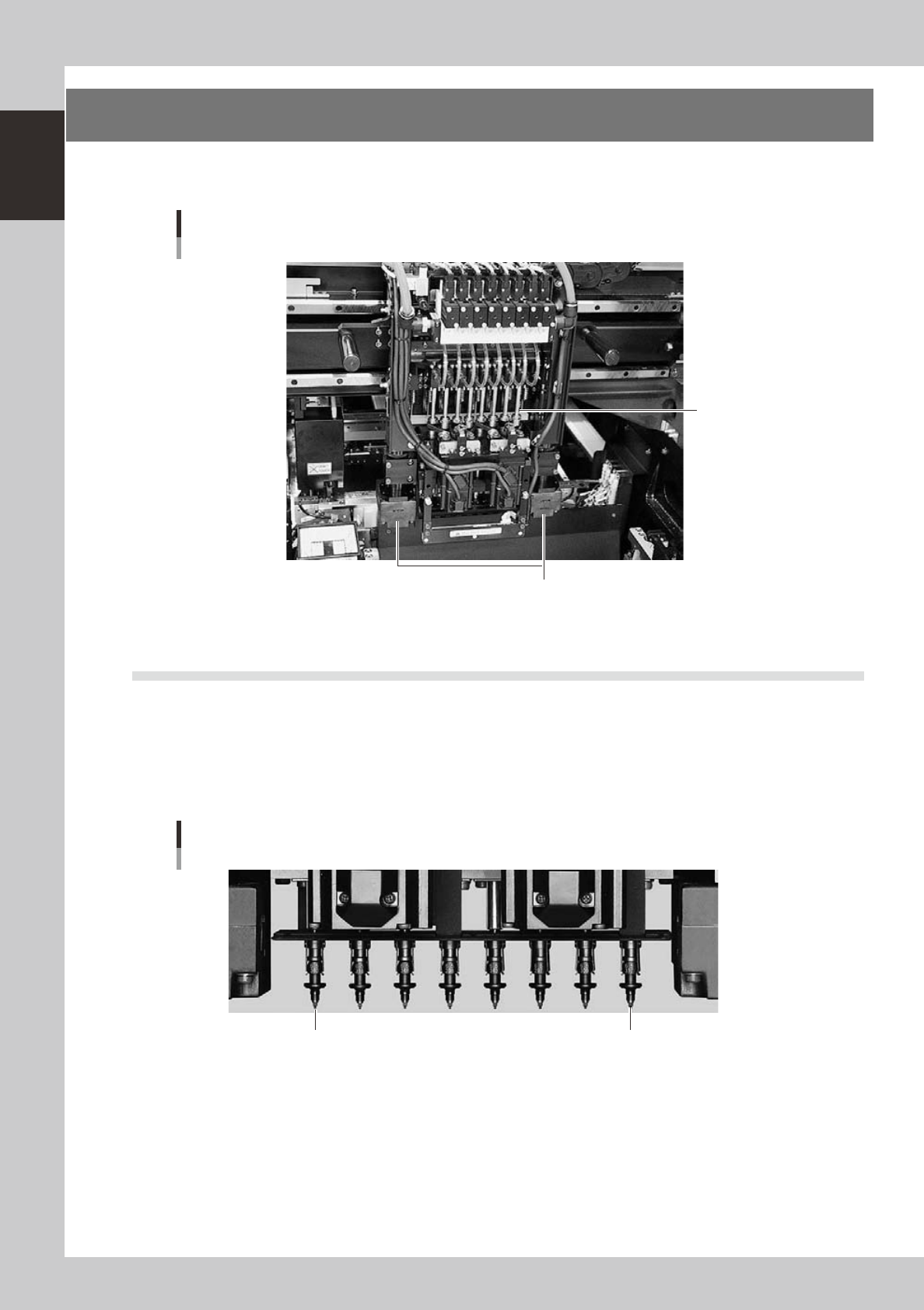
3. Head assembly
The head assembly is mounted on the XY arms and moves to pick up and place components. The following
sections describe the head assembly configurations and nozzle types.
head assembly
Moving camera/Lighting unit
Inner side: Fiducial camera
Outer side: Teaching camera
Eight-in-line multi-head
23115-M3-00
3.1 Component pick-and-place head
3.1.1 Eight-in-line multi-head (FNC) assembly
The eight-in-line multi-head assembly has 8 heads arranged in a row to pick up and mount components at high
speeds. Head numbers are designated from 1 to 8, from the right as viewed from the front of the head
assembly. The spacing of adjacent nozzles attached to the head assembly is 16mm, which is identical to the
pitch of the feeder installation holes on the feeder plates.
Head 8 Head 1
Eight-in-line multi-head
23105-M3-00