YG300_Ope_E.pdf - 第27页
xvii Safety instructions 3 . 3 L a b e l p o s i t i o n s T h e f o l l o w i n g w a r n i n g / c a u t i o n l a b e l s a r e a t t a c h e d t o t h e Y A M A H A p r o d u c t s t o e n s u r e s a f e a n d c o r…
xvi
Safety instructions
n
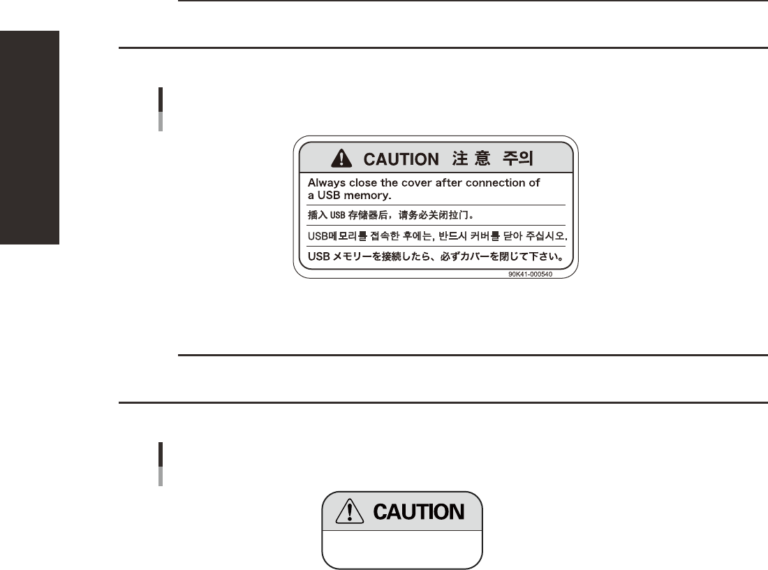
Caution instruction
c
CAUTION
Before operating the FD or USB memory drive to copy data, always close the media access cover to prevent dust from
adhering to the FD or USB port and to protect the floppy disk or USB memory device from electrostatic noise.
n
Applicable machines All YG series machines
Close cover before operating FDD or USB memory drive
93117-LC-00
n
Caution instruction
c
CAUTION
Use specified voltage to make correct connection. Using a connection voltage other than specified can damage the
machine or cause faulty operation.
n
Applicable machines All machines
AC208V INPUT
Use correct voltage
93118-LC-00
xvii
Safety instructions
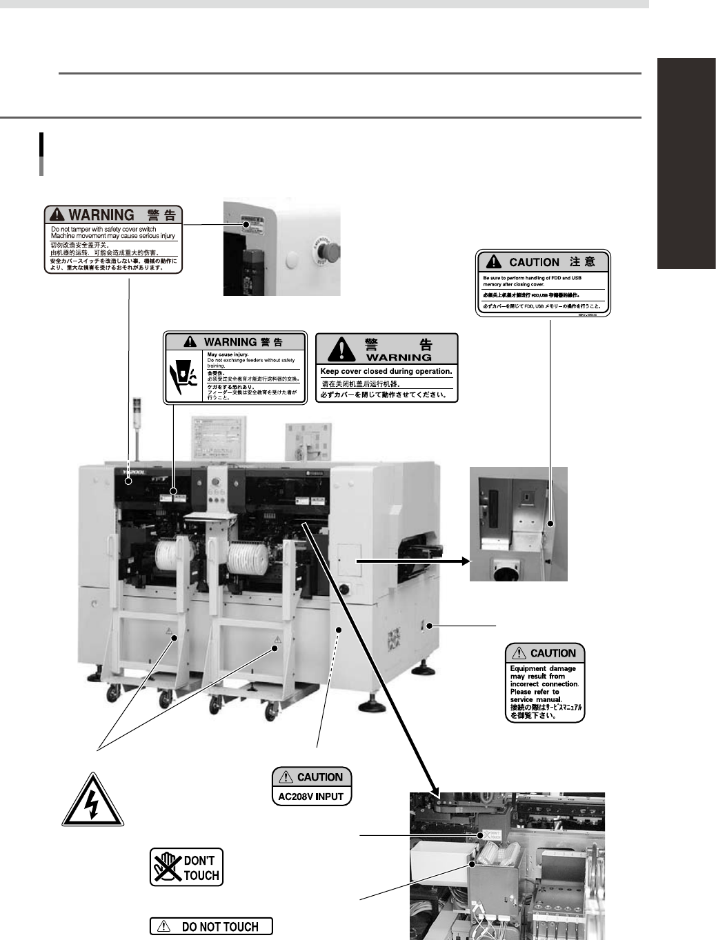
3.3 Label positions
The following warning/caution labels are attached to the YAMAHA products to ensure safe and correct use.
Check that the information on each label is clearly legible and comply with the instructions.
n
NOTE
Basically, labels are attached to the positions shown below, although they may differ slightly depending on the
machine model.
Warning/caution labels
Example of YG200L
N Open/close cover (safety cover) inner side (front and rear)
N Open/close cover (front and rear)
N Media access door inner side
N Lower panels (front, rear, and right on rear)
N Behind panel
N Right side and left side
N Fiducial camera (all tables)
N Multi-vision camera cover edge (all tables)
93201-F4-00

Chapter 1 Part names and functions
Contents
1. Machine main unit 1-1
2. Operation panel and data input unit 1-
4
2.1 Keyboard and mouse 1-4
2.2 Operation panel buttons 1-
5
3. Head assembly 1-6
3.1 Component pick-and-place head 1-6
3.1.1 Eight-in-line multi-head (FNC) assembly 1-6
3.2 Nozzle types 1-7
3.2.1 Nozzles for the eight-in-line head assemblies 1-7
3.3 Nozzle station (option) 1-8
4. Component supply section 1-9
4.1 Supplying components from feeder plates 1-9
4.1.1 Fixed feeder plates 1-9
4.1.2 Feeder exchange carriage 1-11
5.
Conveyor unit and component recognition system
1-13
6. Machine layout 1-1
4
7. Axis configuration 1-1
7
8. Side-view camera 1-1
8
9. Blow station 1-1
9
9.1 Performing a nozzle shaft blow 1-20