YG300_Ope_E.pdf - 第42页
1-14 1 Part names and functions 6 . M a c h i n e l a y o u t T h i s m a c h i n e h a s t h e f o l l o w i n g l a y o u t a n d c o n f i g u r a t i o n . Machine la yout Common to right-to-left and left-to-right bo…
1-13
1
Part names and functions
5.
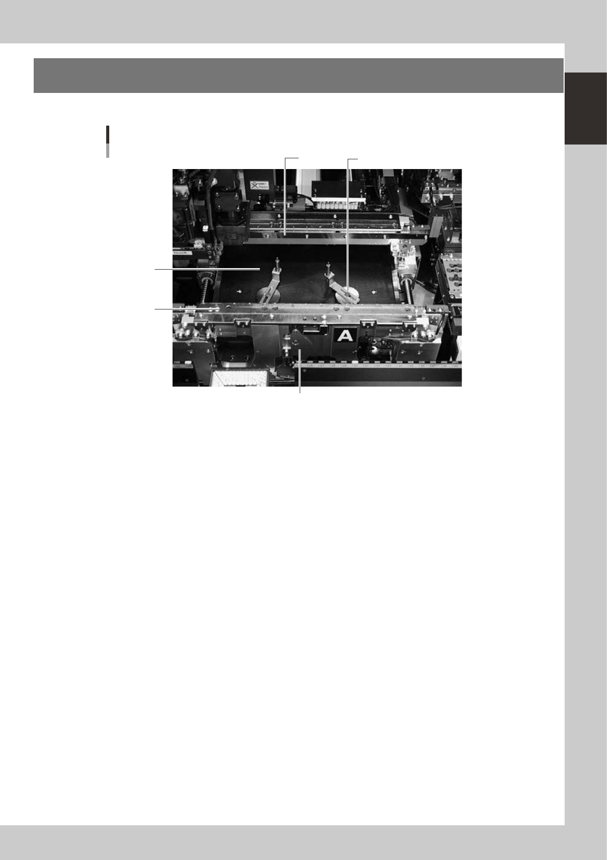
Conveyor unit and component recognition system
The conveyor unit used to clamp a board in mounting position is described below.
3
1
Conveyor units
2
4
5
23113-M3-00
1. Main stopper
When a board is carried in on the conveyor, the main stopper halts travel of the board in the component mounting
position. (Double stopper is optional.)
2. Push-up plate
The push-up plate clamps the board up against the conveyor rails, with the supporter pins attached by magnet on the
push-up plate.
3. Push-up pins
These pins are arranged on the push-up plate and secure the board by pushing it up from the bottom.
4. Board flap
This holds the edge of the board from above when the board is clamped, and can be moved outward or inward during
conveyor unit setup.
5. Clamp lever
Use this lever to lock or unlock the board flap.
1-14
1
Part names and functions
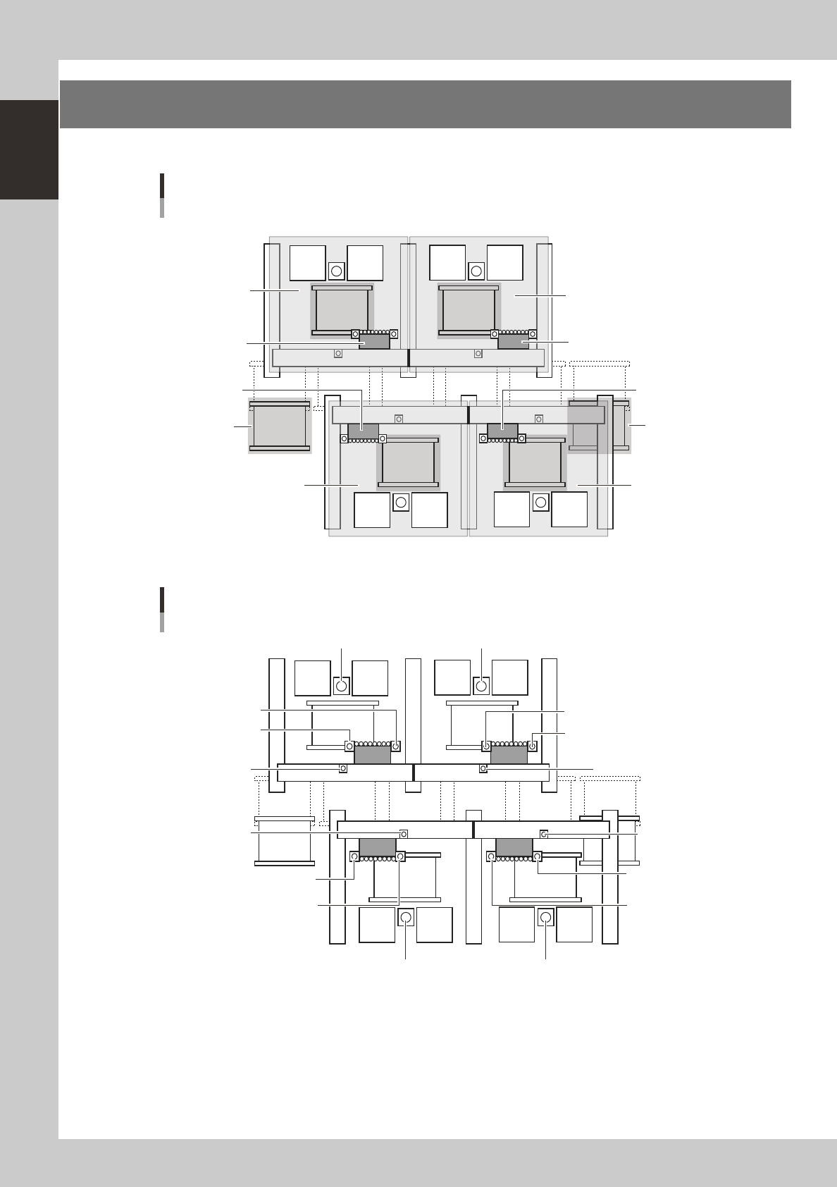
6. Machine layout
This machine has the following layout and configuration.
Machine layout
Common to right-to-left and left-to-right board flow
Placement table D
Placement table B
Head unit B
Head unit D
Head unit C
Head unit A
Placement table C Placement table A
Placement stage B
Right transport
stage
Placement stage APlacement stage C
Placement stage D
Left transport
stage
23114-M3-00
Camera layout
Common to right-to-left and left-to-right board flow
Side-view camera B
Side-view camera D
Side-view camera C
Side-view camera A
Multi-view camera D
Multi-view camera C Multi-view camera A
AC
BD
Multi-view camera B
Fiducial camera B1
(for mark recognition)
Fiducial camera B2
(for mark recognition)
Fiducial camera D1
(for mark recognition)
Fiducial camera D2
(for mark recognition)
Fiducial camera C1
(for mark recognition)
Fiducial camera C2
(for mark recognition)
Fiducial camera A1
(for mark recognition)
Fiducial camera A2
(for mark recognition)
23115-M3-00
1-15
1
Part names and functions
A
BCD
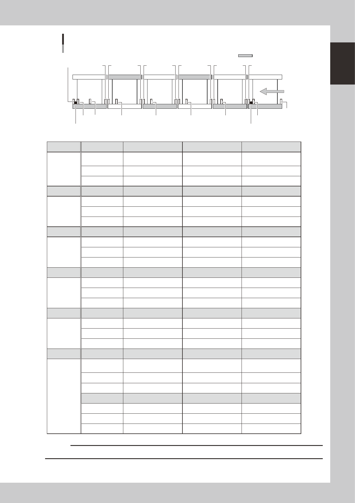
Conveyor sensor positions
Right-to-left board flow
1
3
Reference (fixed) conveyor
Left conveyor
Right conveyor
Board
467910
11
1213
1418 17
1516
19
58
Standby stopperExit stopper
2
23116-M3-00
Unit No. 1 2 3
Right
conveyor
Use Entrance detection
Standby position
detection
Hazard detection
Address N0100612 N0100613 N0100614
Name IN_CONV_CONV1_ENT IN_CONV_CONV1_RCV IN_CONV_CONV1_END
Unit No. 4 5 6
Stage A Use Hazard detection Board detection Hazard detection
Address N0100691 N0100692 N0100693
Name IN_CONV_CONV2_ENT IN_CONV_CONV2_RCV IN_CONV_CONV2_END
Unit No. 7 8 9
Stage B Use Hazard detection Board detection Hazard detection
Address N01006A4 N01006A5 N01006A6
Name IN_CONV_CONV3_ENT IN_CONV_CONV3_RCV IN_CONV_CONV3_END
Unit No. 10 11 12
Stage C Use Hazard detection Board detection Hazard detection
Address N0100811 N0100812 N0100813
Name IN_CONV_CONV4_ENT IN_CONV_CONV4_RCV IN_CONV_CONV4_END
Unit No. 13 14 15
Stage D Use Hazard detection Board detection Hazard detection
Address N0100824 N0100825 N0100826
Name IN_CONV_CONV5_ENT IN_CONV_CONV5_RCV IN_CONV_CONV5_END
Unit No. 16 17 18
Left
conveyor
Use Hazard detection
Intermediate position
detection
Exit detection
Address N0100792 N0100795 N0100793
Name IN_CONV_CONV6_ENT IN_CONV_CONV6_MID IN_CONV_CONV6_RCV
No. 19
Use Hazard detection
Address N0100794
Name IN_CONV_CONV6_END
c
CAUTION
Conveyor's board sensors may fail to detect a production board if it has a slit or cutout.