YG300_Ope_E.pdf - 第66页
2-13 2 Basic operation 1 . [C o n v e y B o a r d ] b u t t o n P r e s s i n g t h i s b u t t o n d i s p l a y s t h e f o l l o w i n g d i a l o g b o x . "Con vey Boar ds" dialog bo x 24 2 0 5 - M 3 -0 0 …
2-12
2
Basic operation
2.3 Unit screen
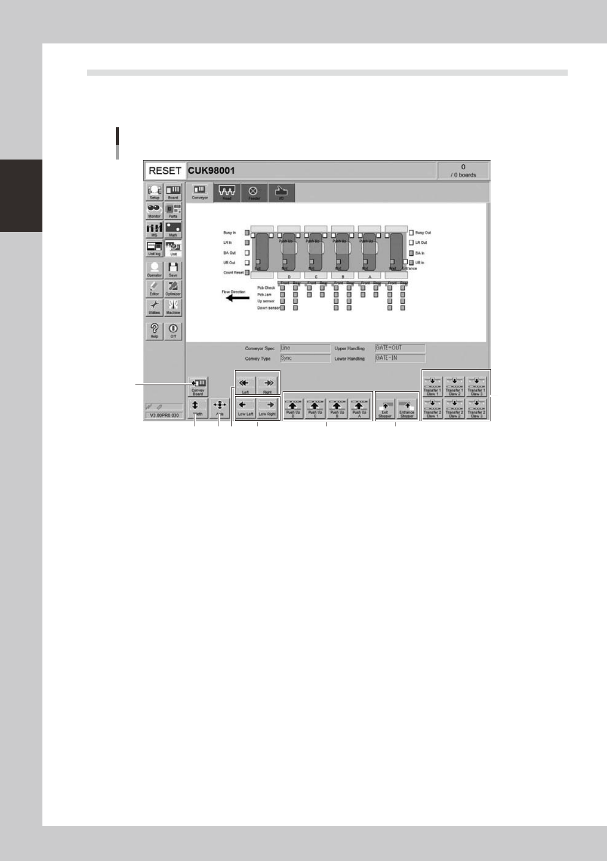
This section describes the manual operation buttons on the Unit screen.
n
Manual conveyor operation
3
1
2 4 6
8
7
Conveyor manual buttons
5
24204-M3-00
2-13
2
Basic operation
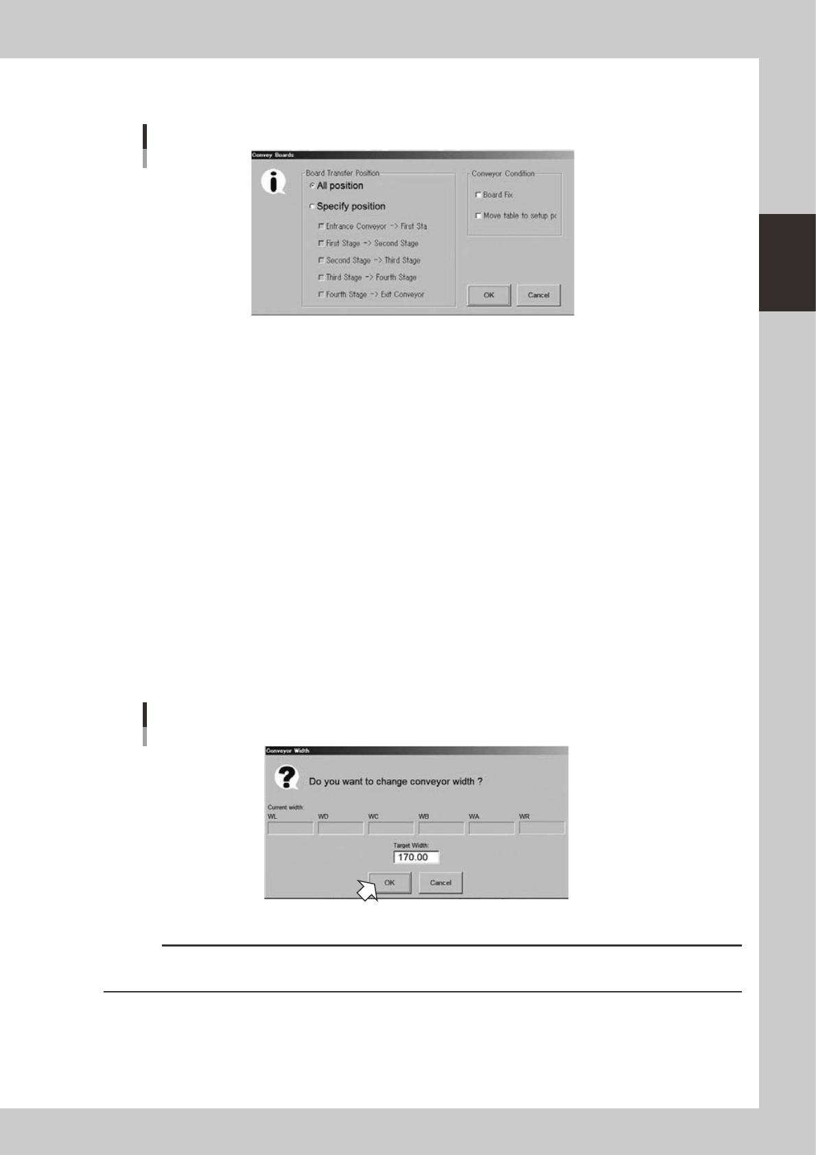
1. [Convey Board] button
Pressing this button displays the following dialog box.
"Convey Boards" dialog box
24205-M3-00
• All positions
Selecting this option button transfers boards in sequence from "Entrance conveyor
→
1st stage", "1st stage
→
2nd stage",
"2nd stage
→
3rd stage", "3rd stage
→
4th stage", and "4th stage
→
exit conveyor".
• Specify position
Selecting this option button transfers boards only in the sections specified with the check boxes under this button. When
all check boxes are selected, this is the same as selecting the "All positions" option button.
• Board Fix
After boards are conveyed, they are clamped on each stage.
• Move table to setup position
After boards are conveyed, each stage moves to the following position.
• Placement stages (A, B, C, D) move to the component placement position.
• Carry-in stage moves to the board carry-in position (where the conveyor line is aligned with the upstream machine)
• Carry-out stage moves to the board carry-out position (where the conveyor line is aligned with the downstream
machine)
2. [Width] button
Use this button to adjust the conveyor width to match the width of boards to be produced.
Pressing this button displays the "Conveyor Width" dialog box. Check the conveyor width and press the [OK] button. The
conveyor rail automatically changes to the specified width.
"Conveyor Width" dialog box
24206-M-00
c
CAUTION
When push-up pins are set on the push-up plate, make sure that they do not touch the conveyor rail while adjusting
the conveyor width.
2-14
2
Basic operation
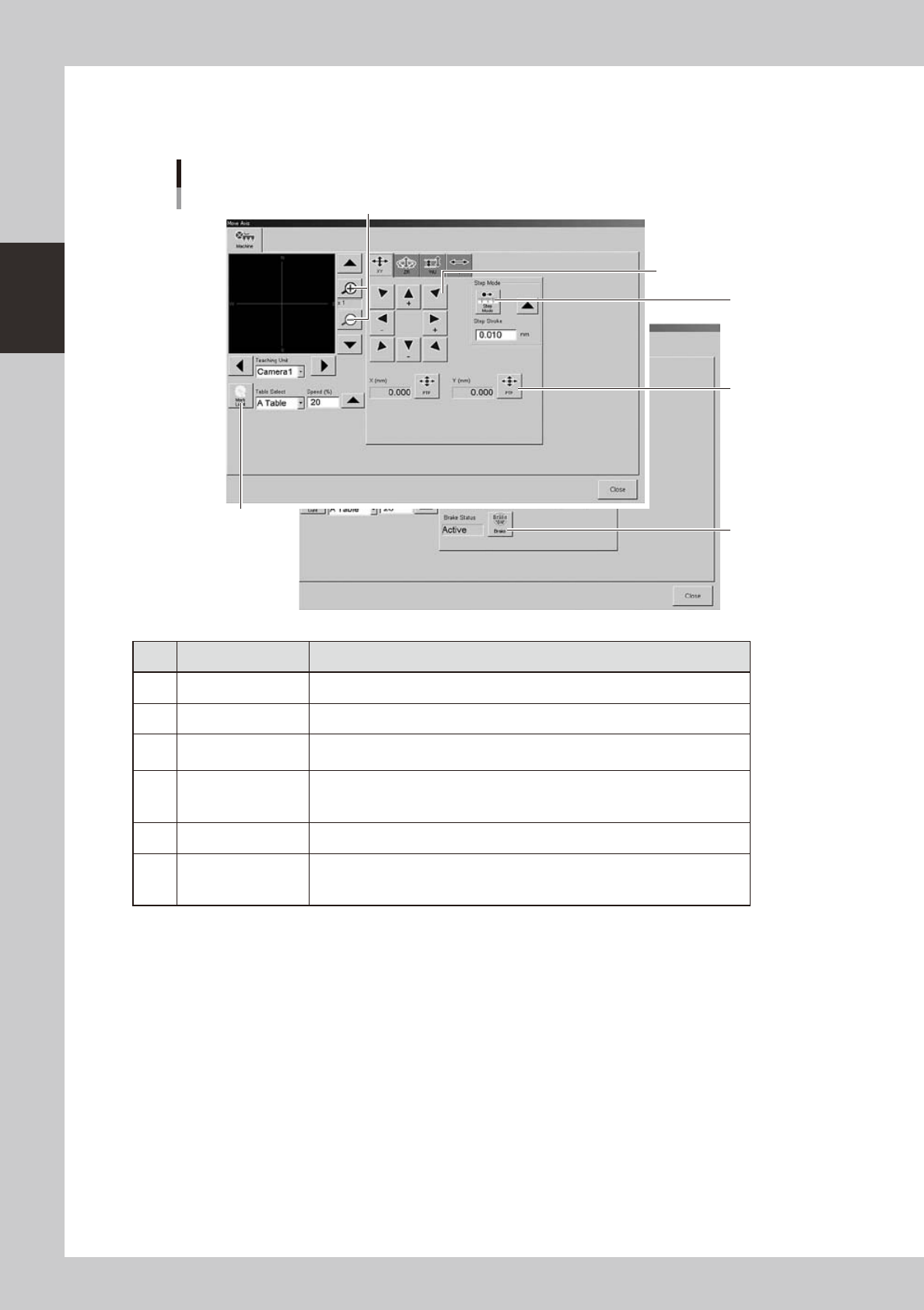
3. [Axis] button
Pressing this button opens the "Move Axis" window as shown below. You can manually move each axis at a specified
step stroke with the arrow buttons or to a specified position with the [PTP] button.
"Move Axis" screen
1
2
3
4
5
6
24207-M3-00
Button name Function
1 Zoom in/out (+, -) Zooms in or out the image. (16 times to 1/16 times)
2 Mark Light Allows changing mark lighting manually. Using this button does not affect data.
3 PTP
Displays the "PTP" dialog box that allows directly specifying the position where
you want to move the selected axis.
4 Step Mode
When this button is pushed in, the selected axis can be moved in "step mode
(inching mode)" with the arrow buttons at a specified step stroke (inching
stroke).
5 Arrow Use these buttons to move the selected axis in the desired direction.
6 Brake
Use this button when you want to release the brake during emergency stop.
(W-axis and PU axis only)
The brake is automatically released when the servo is turned on.