YG300_Ope_E.pdf - 第40页
1-12 1 Part names and functions n M o u n t e r s i d e Switch and sensors on the mounter 3 1 2 4 23 1 1 2 - M 3 -0 0 1 C l a m p O N / O F F s w i t c h A f t e r i n s t a l l i n g t h e f e e d e r e x c h a n g e c …
1-11
1
Part names and functions
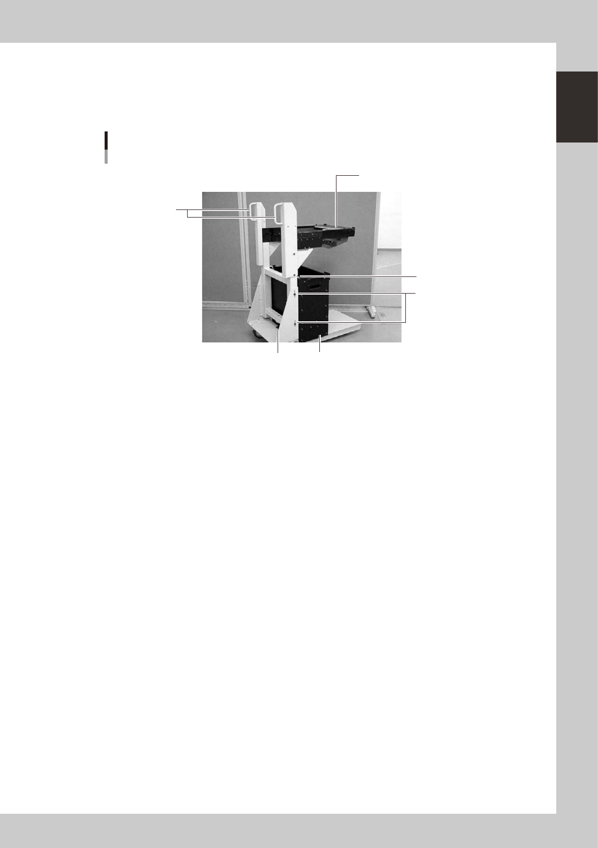
4.1.2 Feeder exchange carriage
The feeder exchange carriage allows feeder setup in advance for the next production boards. The feeders on
the feeder exchange carriage can be changed at one time.
n
Feeder exchange carriage
Feeder exchange carriage
1
2
5
4
6
3
23111-M3-00
1 Handle
Use this handle to move and position the feeder exchange carriage.
2 Feeder plate
Up to 20 or 24 tape feeders (8mm tape feeders) can be installed on this feeder plate.
3 Vertical clamp bolts
If necessary to adjust the feeder plate height, loosen these bolts and change their clamping positions by turning the
height adjustment bolt 6 to match the mounter height.
4 Empty tape dump box (option)
This box is for catching empty tape after components have been picked up.
5 Empty tape dump box holder
This holder prevents the tape dump box (option) from falling.
6 Height adjustment bolt
After loosening the vertical clamp bolts 3, turn this bolt to adjust the feeder plate height to match the mounter height.
1-12
1
Part names and functions
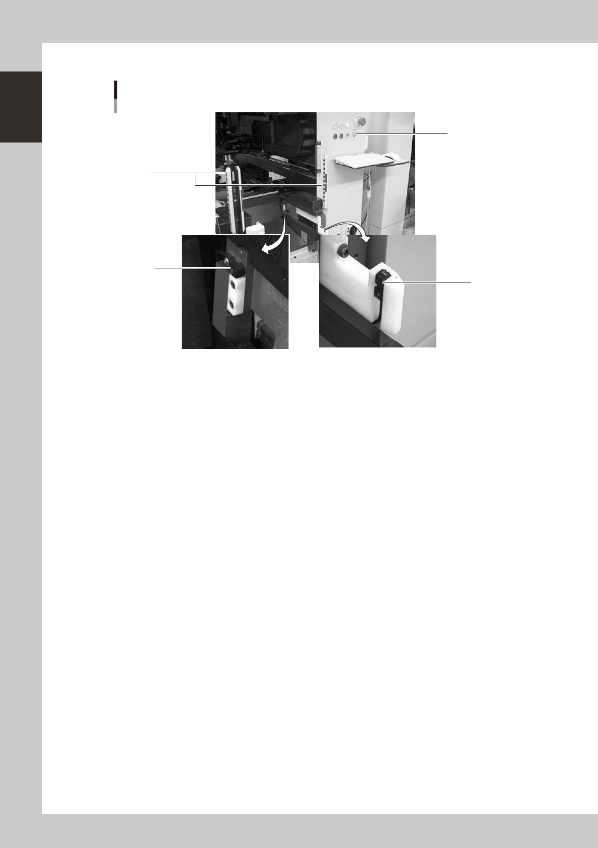
n
Mounter side
Switch and sensors on the mounter
3
1
2
4
23112-M3-00
1 Clamp ON/OFF switch
After installing the feeder exchange carriage into the mounter, turn this switch to the left (ON) to raise the feeder plate of
the feeder exchange carriage and automatically clamp it into the position. To unclamp, turn this switch to the right (OFF).
2 Forward end sensor
When the feeder exchange carriage is fully installed into the mounter, the green LED on this sensor lights up.
3 Area sensor for non-stop operation (option)
This safety area sensor is attached to mounters with a non-stop function. When the feeder exchange carriage is installed
into the mounter, the entrance sensors located at the front (or rear) of the mounter detect the feeder exchange carriage
and turn off this area sensor function.
4 Entrance sensor for non-stop feeder exchange carriage (option)
This sensor is attached to the front (or rear) of mounters with a non-stop function. When the feeder exchange carriage is
installed into the mounter, this sensor detects the feeder exchange carriage and turns off the area sensor function to
permit removing and installing the feeder exchange carriage even during automatic operation.
1-13
1
Part names and functions
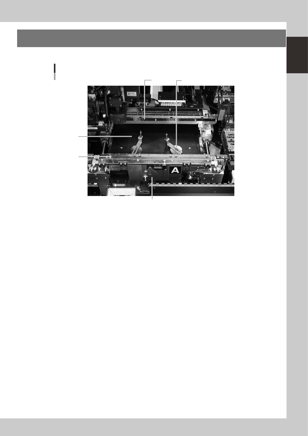
5.
Conveyor unit and component recognition system
The conveyor unit used to clamp a board in mounting position is described below.
3
1
Conveyor units
2
4
5
23113-M3-00
1. Main stopper
When a board is carried in on the conveyor, the main stopper halts travel of the board in the component mounting
position. (Double stopper is optional.)
2. Push-up plate
The push-up plate clamps the board up against the conveyor rails, with the supporter pins attached by magnet on the
push-up plate.
3. Push-up pins
These pins are arranged on the push-up plate and secure the board by pushing it up from the bottom.
4. Board flap
This holds the edge of the board from above when the board is clamped, and can be moved outward or inward during
conveyor unit setup.
5. Clamp lever
Use this lever to lock or unlock the board flap.